Lenovo U310 Laptop Hardware Maintenance Manual - IdeaPad U310, U410, U310 Touc - Page 39
U310/U310 Touch, Removal steps of battery pack continued
 |
View all Lenovo U310 Laptop manuals
Add to My Manuals
Save this manual to your list of manuals |
Page 39 highlights
Lenovo IdeaPad U310/U410 U310/U410 Touch Figure 1. Removal steps of battery pack (continued) Open the back cover along the device frame with a flat blade in the direction shown by arrows and then lift the back cover in the direction shown by arrow c. c U310/U310 Touch After removing the bottom cover, turn over the console and lay it flat on the work space. As shown in the illustration below, absorbers (Part No. XXXXXX) will be attached onto three red areas: A, B and C. Use the corresponding size of absorber, and apply it to the machine from the blue baselines pointed to by the blue arrow in the illustration below. When the starting positions are fixed, press the absorber to make it flat. Affix them in the areas of A, B and C in order. 35
-
 1
1 -
2
-
3
-
4
-
5
-
6
-
7
-
8
-
9
-
10
-
11
-
12
-
13
-
14
-
15
-
16
-
17
-
18
-
19
-
20
-
21
-
22
-
23
-
24
-
25
-
26
-
27
-
28
-
29
-
30
-
31
-
32
-
33
-
 34
34 -
 35
35 -
 36
36 -
 37
37 -
 38
38 -
 39
39 -
 40
40 -
 41
41 -
 42
42 -
 43
43 -
 44
44 -
45
-
46
-
47
-
48
-
49
-
50
-
51
-
52
-
53
-
54
-
55
-
56
-
57
-
58
-
59
-
60
-
61
-
62
-
63
-
64
-
65
-
66
-
67
-
68
-
69
-
70
-
71
-
72
-
73
-
74
-
75
-
76
-
77
-
78
-
79
-
80
-
81
-
82
-
83
-
84
-
85
-
86
-
87
-
88
-
89
-
90
-
91
-
92
-
93
-
94
-
95
-
96
-
97
-
98
-
99
-
100
-
101
-
102
-
103
-
104
-
105
-
106
-
107
-
108
-
109
-
110
-
111
-
112
-
113
-
114
-
115
 |
 |

Lenovo IdeaPad U310/U410 U310/U410 Touch
35
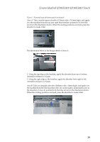
Figure 1. Removal steps of battery pack (continued)
Open the back cover along the device frame with a flat blade in the direction
shown by arrows and then lift the back cover in the direction shown by arrow
.
U310/U310 Touch
After removing the bottom cover, turn over the console and lay it flat on the
work space. As shown in the illustration below, absorbers (Part No. XXXXXX)
will be attached onto three red areas: A, B and C.
Use the corresponding size of absorber, and apply it to the machine from the blue
baselines pointed to by the blue arrow in the illustration below. When the
starting positions are fixed, press the absorber to make it flat. Affix them in the
areas of A, B and C in order.
c
c