Lenovo U310 Laptop Hardware Maintenance Manual - IdeaPad U310, U410, U310 Touc - Page 45
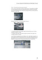
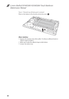
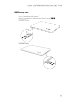
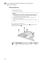
B, then apply it to the machine.
 |
View all Lenovo U310 Laptop manuals
Add to My Manuals
Save this manual to your list of manuals |
Page 45 highlights
Lenovo IdeaPad U310/U410 U310/U410 Touch Figure 1. Removal steps of battery pack (continued) Area C: The illustration below shows the actual procedure. The absorber can be aligned with the right edge of the plastic rectangular frame indicated by the blue baseline. Then use your fingers on your left hand or a jig to relocate at the ventilation aperture, i.e. move the absorber down, and align it with the blue baseline of the absorber of Area B. Area C: Move the absorber down to the blue baseline on the bottom edge of Area B, then apply it to the machine. Note: The yellow area in this illustration corresponds to the location of the black Mylar, which is on the other side of the absorber. The illustration below is the design sketch of Area C. 41
-
 1
1 -
2
-
3
-
4
-
5
-
6
-
7
-
8
-
9
-
10
-
11
-
12
-
13
-
14
-
15
-
16
-
17
-
18
-
19
-
20
-
21
-
22
-
23
-
24
-
25
-
26
-
27
-
28
-
29
-
30
-
31
-
32
-
33
-
34
-
35
-
36
-
37
-
38
-
39
-
 40
40 -
 41
41 -
 42
42 -
 43
43 -
 44
44 -
 45
45 -
 46
46 -
 47
47 -
 48
48 -
 49
49 -
 50
50 -
51
-
52
-
53
-
54
-
55
-
56
-
57
-
58
-
59
-
60
-
61
-
62
-
63
-
64
-
65
-
66
-
67
-
68
-
69
-
70
-
71
-
72
-
73
-
74
-
75
-
76
-
77
-
78
-
79
-
80
-
81
-
82
-
83
-
84
-
85
-
86
-
87
-
88
-
89
-
90
-
91
-
92
-
93
-
94
-
95
-
96
-
97
-
98
-
99
-
100
-
101
-
102
-
103
-
104
-
105
-
106
-
107
-
108
-
109
-
110
-
111
-
112
-
113
-
114
-
115
 |
 |
