Lenovo U310 Laptop Hardware Maintenance Manual - IdeaPad U310, U410, U310 Touc - Page 46
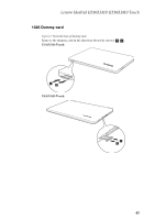
When the above steps are completed, use the illustration below to check
 |
View all Lenovo U310 Laptop manuals
Add to My Manuals
Save this manual to your list of manuals |
Page 46 highlights
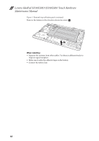
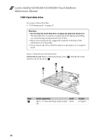
Lenovo IdeaPad U310/U410 U310/U410 Touch Hardware Maintenance Manual Figure 1. Removal steps of battery pack (continued) Area D: Take a rectangular absorber (18mm wide x 35mm high), and apply it to the machine from the blue baselines pointed to by the blue arrow in the illustration below. When the starting positions are fixed, press the absorber to make it flat. Note: Align its top edge with the bottom edge of the white laser area on the bottom cover; Align its left edge with the edge of the black plastic casing. The illustration below is the design sketch of Area D; When the above steps are completed, use the illustration below to check to ensure that all absorbers are in the right locations. Then press the absorbers, until they are flat and there are no bubbles, no curled edges. This is the end of the process of applying absorbers to the bottom cover. Next, apply Cu foils to the upper cover. 42
-
 1
1 -
2
-
3
-
4
-
5
-
6
-
7
-
8
-
9
-
10
-
11
-
12
-
13
-
14
-
15
-
16
-
17
-
18
-
19
-
20
-
21
-
22
-
23
-
24
-
25
-
26
-
27
-
28
-
29
-
30
-
31
-
32
-
33
-
34
-
35
-
36
-
37
-
38
-
39
-
40
-
 41
41 -
 42
42 -
 43
43 -
 44
44 -
 45
45 -
 46
46 -
 47
47 -
 48
48 -
 49
49 -
 50
50 -
 51
51 -
52
-
53
-
54
-
55
-
56
-
57
-
58
-
59
-
60
-
61
-
62
-
63
-
64
-
65
-
66
-
67
-
68
-
69
-
70
-
71
-
72
-
73
-
74
-
75
-
76
-
77
-
78
-
79
-
80
-
81
-
82
-
83
-
84
-
85
-
86
-
87
-
88
-
89
-
90
-
91
-
92
-
93
-
94
-
95
-
96
-
97
-
98
-
99
-
100
-
101
-
102
-
103
-
104
-
105
-
106
-
107
-
108
-
109
-
110
-
111
-
112
-
113
-
114
-
115
 |
 |
