Lenovo U310 Laptop Hardware Maintenance Manual - IdeaPad U310, U410, U310 Touc - Page 61
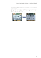
thoroughly then affix copper foil., part has good contact. If there has been a white label attached
 |
View all Lenovo U310 Laptop manuals
Add to My Manuals
Save this manual to your list of manuals |
Page 61 highlights
Lenovo IdeaPad U310/U410 U310/U410 Touch Figure 6. Removal steps of fan assembly and heat sink assembly (continued) U310/U310 Touch: After removing fan, attach copper foil into the areas outlined by red in the illustration below. The copper foil should start from the left edge of the system board (noted by the blue baseline) and over the area marked in blue. Do not put the copper foil over the white cable. Note: 1. In the area indicated by the far left yellow circle, ensure good contact between copper foil and the protruding white wire. 2. In the area indicated by the center yellow circle, attach directly to the flat surface area, and make sure there is good adhesion between copper foil and flat surface area. Avoid contact with LVDS cable: it may be necessary to lift up the cable and then restore it to its ordinal position after affixing the copper foil. 3. In the area indicated by the far right yellow circle, ensure small copper plate part has good contact. If there has been a white label attached, first clean plate thoroughly then affix copper foil. Under the fan and on top of the main structure, attach copper foil according to the illustration below. Note: In the area noted by the green rectangle, attach directly to the main structure. In the areas outlined by red ovals, take care to avoid the copper foil breaking at these points, and assure good adhesion to the metal base. 57
-
 1
1 -
2
-
3
-
4
-
5
-
6
-
7
-
8
-
9
-
10
-
11
-
12
-
13
-
14
-
15
-
16
-
17
-
18
-
19
-
20
-
21
-
22
-
23
-
24
-
25
-
26
-
27
-
28
-
29
-
30
-
31
-
32
-
33
-
34
-
35
-
36
-
37
-
38
-
39
-
40
-
41
-
42
-
43
-
44
-
45
-
46
-
47
-
48
-
49
-
50
-
51
-
52
-
53
-
54
-
55
-
 56
56 -
 57
57 -
 58
58 -
 59
59 -
 60
60 -
 61
61 -
 62
62 -
 63
63 -
 64
64 -
 65
65 -
 66
66 -
67
-
68
-
69
-
70
-
71
-
72
-
73
-
74
-
75
-
76
-
77
-
78
-
79
-
80
-
81
-
82
-
83
-
84
-
85
-
86
-
87
-
88
-
89
-
90
-
91
-
92
-
93
-
94
-
95
-
96
-
97
-
98
-
99
-
100
-
101
-
102
-
103
-
104
-
105
-
106
-
107
-
108
-
109
-
110
-
111
-
112
-
113
-
114
-
115
 |
 |
