Lenovo U310 Laptop Hardware Maintenance Manual - IdeaPad U310, U410, U310 Touc - Page 41
The illustration below is the design sketch of Area C., If attaching starting from blue arrow 1
 |
View all Lenovo U310 Laptop manuals
Add to My Manuals
Save this manual to your list of manuals |
Page 41 highlights
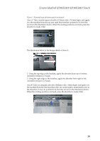
Lenovo IdeaPad U310/U410 U310/U410 Touch Figure 1. Removal steps of battery pack (continued) The illustration below is the design sketch of Area B. Note: 1. The yellow rectangles 1 and 2 below show rubber protrusions. Absorber should not cover these. 2. Arched line 3, absorber should be cut along the arched line, against the black mylar alignment. It must not overlap, so it does not interfere with fan. Area C: Take a stepped-shaped absorber (100mm wide x 32mm high), and apply it to the machine from the blue baselines (either arrow 1 or arrow 2) pointed to by the blue arrow in the illustration below. When the starting positions are fixed, press the absorber to make it flat. Area B The illustration below is the design sketch of Area C. Note: If attaching starting from blue arrow 1, take care that the absorber does not overlap in the area indicated by the red oval. Take care that the absorber does not extend past the area indicated by the yellow line below, otherwise it will interfere with the fan. Area B 37
-
 1
1 -
2
-
3
-
4
-
5
-
6
-
7
-
8
-
9
-
10
-
11
-
12
-
13
-
14
-
15
-
16
-
17
-
18
-
19
-
20
-
21
-
22
-
23
-
24
-
25
-
26
-
27
-
28
-
29
-
30
-
31
-
32
-
33
-
34
-
35
-
 36
36 -
 37
37 -
 38
38 -
 39
39 -
 40
40 -
 41
41 -
 42
42 -
 43
43 -
 44
44 -
 45
45 -
 46
46 -
47
-
48
-
49
-
50
-
51
-
52
-
53
-
54
-
55
-
56
-
57
-
58
-
59
-
60
-
61
-
62
-
63
-
64
-
65
-
66
-
67
-
68
-
69
-
70
-
71
-
72
-
73
-
74
-
75
-
76
-
77
-
78
-
79
-
80
-
81
-
82
-
83
-
84
-
85
-
86
-
87
-
88
-
89
-
90
-
91
-
92
-
93
-
94
-
95
-
96
-
97
-
98
-
99
-
100
-
101
-
102
-
103
-
104
-
105
-
106
-
107
-
108
-
109
-
110
-
111
-
112
-
113
-
114
-
115
 |
 |
