Lenovo U310 Laptop Hardware Maintenance Manual - IdeaPad U310, U410, U310 Touc - Page 62
The yellow area in the middle: apply the foil directly to the hinge, and ensure
 |
View all Lenovo U310 Laptop manuals
Add to My Manuals
Save this manual to your list of manuals |
Page 62 highlights
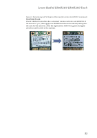
Lenovo IdeaPad U310/U410 U310/U410 Touch Hardware Maintenance Manual Figure 6. Removal steps of fan assembly and heat sink assembly (continued) U410/U410 Touch: The second location - under the fan. Remove the 7 screws on the fan and the interface, then remove the fan. After the fan has been removed, apply Cu foil to the red areas in the illustration below, starting from the blue baseline on the edge of the system board on the left, and along the horizontal blue baseline of the metal component. (Cover a little more than the horizontal baseline.) Note: 1.The yellow area on the left: ensure there's a good connection between the foil and the white ribbon cable. 2.The yellow area in the middle: apply the foil directly to the hinge, and ensure there's a good connection. 3. The yellow area on the right: ensure the connection is good on the termination block. If there is a white label in this area, remove it and clean the area before applying the foil. 58
-
 1
1 -
2
-
3
-
4
-
5
-
6
-
7
-
8
-
9
-
10
-
11
-
12
-
13
-
14
-
15
-
16
-
17
-
18
-
19
-
20
-
21
-
22
-
23
-
24
-
25
-
26
-
27
-
28
-
29
-
30
-
31
-
32
-
33
-
34
-
35
-
36
-
37
-
38
-
39
-
40
-
41
-
42
-
43
-
44
-
45
-
46
-
47
-
48
-
49
-
50
-
51
-
52
-
53
-
54
-
55
-
56
-
 57
57 -
 58
58 -
 59
59 -
 60
60 -
 61
61 -
 62
62 -
 63
63 -
 64
64 -
 65
65 -
 66
66 -
 67
67 -
68
-
69
-
70
-
71
-
72
-
73
-
74
-
75
-
76
-
77
-
78
-
79
-
80
-
81
-
82
-
83
-
84
-
85
-
86
-
87
-
88
-
89
-
90
-
91
-
92
-
93
-
94
-
95
-
96
-
97
-
98
-
99
-
100
-
101
-
102
-
103
-
104
-
105
-
106
-
107
-
108
-
109
-
110
-
111
-
112
-
113
-
114
-
115
 |
 |
