Lenovo U310 Laptop Hardware Maintenance Manual - IdeaPad U310, U410, U310 Touc - Page 44
it to the machine from the blue baselines pointed to by the blue arrows in
 |
View all Lenovo U310 Laptop manuals
Add to My Manuals
Save this manual to your list of manuals |
Page 44 highlights
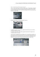
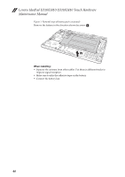
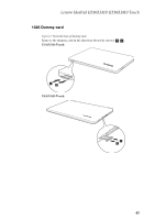
Lenovo IdeaPad U310/U410 U310/U410 Touch Hardware Maintenance Manual Figure 1. Removal steps of battery pack (continued) The illustration below is the design sketch of Area B. Area C: Take a rectangular absorber (50mm wide x 45mm high) and a black Mylar (50mm wide x 20mm high - the height may vary), and adhere them to each other as follows. Note: The adhesive sides of the black Mylar and the absorber should face the same direction. adhesive side adhesive side Area C: Take the treated absorber as shown in the illustration above, and apply it to the machine from the blue baselines pointed to by the blue arrows in the illustration below. When the starting positions are fixed, press the absorber to make it flat. Note: The yellow area in this illustration corresponds to the location of the black Mylar on the absorber. 40
-
 1
1 -
2
-
3
-
4
-
5
-
6
-
7
-
8
-
9
-
10
-
11
-
12
-
13
-
14
-
15
-
16
-
17
-
18
-
19
-
20
-
21
-
22
-
23
-
24
-
25
-
26
-
27
-
28
-
29
-
30
-
31
-
32
-
33
-
34
-
35
-
36
-
37
-
38
-
 39
39 -
 40
40 -
 41
41 -
 42
42 -
 43
43 -
 44
44 -
 45
45 -
 46
46 -
 47
47 -
 48
48 -
 49
49 -
50
-
51
-
52
-
53
-
54
-
55
-
56
-
57
-
58
-
59
-
60
-
61
-
62
-
63
-
64
-
65
-
66
-
67
-
68
-
69
-
70
-
71
-
72
-
73
-
74
-
75
-
76
-
77
-
78
-
79
-
80
-
81
-
82
-
83
-
84
-
85
-
86
-
87
-
88
-
89
-
90
-
91
-
92
-
93
-
94
-
95
-
96
-
97
-
98
-
99
-
100
-
101
-
102
-
103
-
104
-
105
-
106
-
107
-
108
-
109
-
110
-
111
-
112
-
113
-
114
-
115
 |
 |
