Lexmark C772N Service Manual - Page 101
Cartridge, contact, assembly, removal on, BASE SENSOR TEST on Developer
 |
UPC - 734646047227
View all Lexmark C772N manuals
Add to My Manuals
Save this manual to your list of manuals |
Page 101 highlights
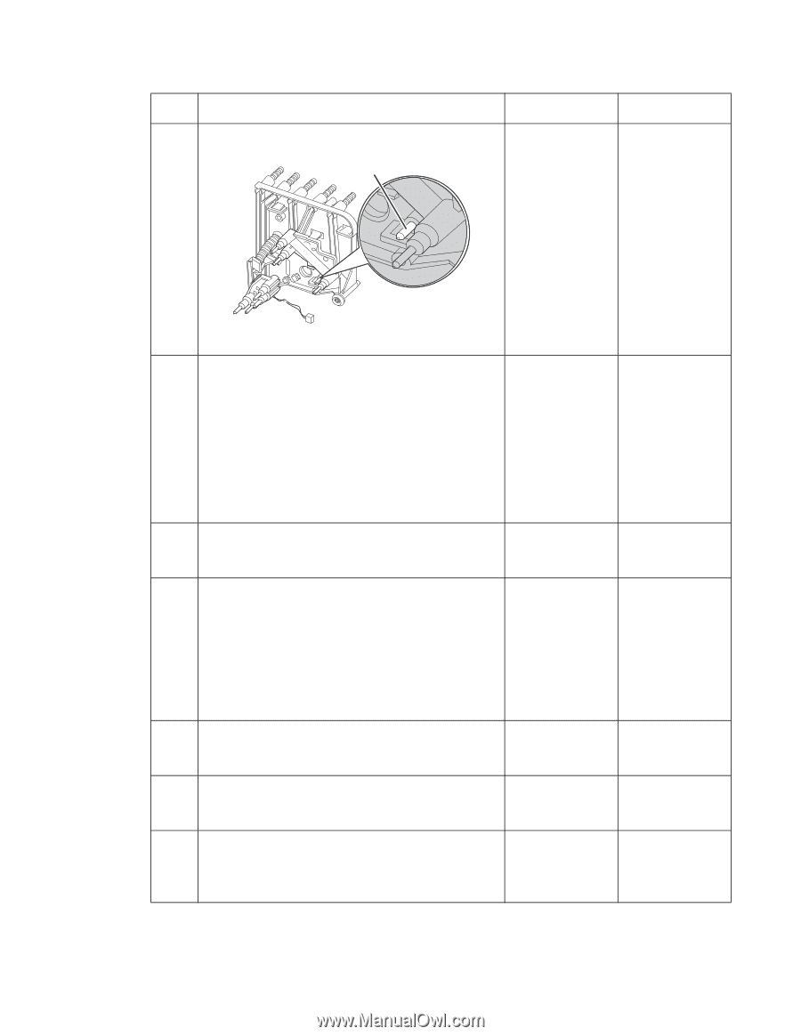
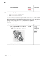
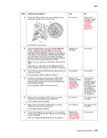
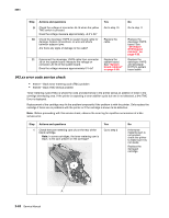
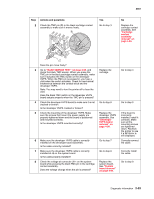
Step 2 Actions and questions Check the TMC pin (B) in the magenta cartridge contact assembly to make sure it moves freely. B 5061 Yes Go to step 3 No Replace the cartridge contact assembly. See "Cartridge contact assembly removal" on page 4-35. Does the pin move freely? 3 Go to the "BASE SENSOR TEST" on page 3-24, and check the magenta TMC sensor. When you press the TMC pin in the magenta cartridge contact assembly, make sure it actuates the TMC switch on the developer HVPS. When the TMC pin is pressed in, you hear a click when the switch actuates. Check for mechanical interference between the contact block and the developer HVPS. Note: You may need to turn the printer off to hear the click. Does the magenta TMC switch on the developer HVPS board actuate properly when the TMC pin is pressed? 4 Check the developer HVPS board to make sure it is not cracked or broken. Is the developer HVPS cracked or broken? 5 Check the mounting of the developer HVPS. Make sure the screws that mount the power supply are properly tightened down and the board is positioned and mounted correctly. Is the developer HVPS mounted correctly? 6 Make sure the developer HVPS cable is correctly installed on the developer board assembly. Is the cable correctly installed? 7 Make sure the developer HVPS cable is correctly installed at J6 on the system board. Is the cable properly installed? 8 Check the voltage at connector J6-6 on the system board while pressing the magenta TMC pin in the cartridge contact assembly. Does the voltage change when the pin is pressed? Replace the cartridge. Go to step 6 Replace the developer HPVS. See "Developer HVPS board removal" on page 4-39. Go to step 7 Go to step 8 Replace the system board. See "System board removal" on page 4-89. Go to step 4 Go to step 5 If the board is incorrectly installed, install it correctly. Make sure all the mounting screws are tightened down. Recheck the printer to see if a 941 Error is still displayed. Correctly connect the cable. Correctly connect the cable. Go to step 9 Diagnostic information 2-59
-
 1
1 -
2
-
3
-
4
-
5
-
6
-
7
-
8
-
9
-
10
-
11
-
12
-
13
-
14
-
15
-
16
-
17
-
18
-
19
-
20
-
21
-
22
-
23
-
24
-
25
-
26
-
27
-
28
-
29
-
30
-
31
-
32
-
33
-
34
-
35
-
36
-
37
-
38
-
39
-
40
-
41
-
42
-
43
-
44
-
45
-
46
-
47
-
48
-
49
-
50
-
51
-
52
-
53
-
54
-
55
-
56
-
57
-
58
-
59
-
60
-
61
-
62
-
63
-
64
-
65
-
66
-
67
-
68
-
69
-
70
-
71
-
72
-
73
-
74
-
75
-
76
-
77
-
78
-
79
-
80
-
81
-
82
-
83
-
84
-
85
-
86
-
87
-
88
-
89
-
90
-
91
-
92
-
93
-
94
-
95
-
 96
96 -
 97
97 -
 98
98 -
 99
99 -
 100
100 -
 101
101 -
 102
102 -
 103
103 -
 104
104 -
 105
105 -
 106
106 -
107
-
108
-
109
-
110
-
111
-
112
-
113
-
114
-
115
-
116
-
117
-
118
-
119
-
120
-
121
-
122
-
123
-
124
-
125
-
126
-
127
-
128
-
129
-
130
-
131
-
132
-
133
-
134
-
135
-
136
-
137
-
138
-
139
-
140
-
141
-
142
-
143
-
144
-
145
-
146
-
147
-
148
-
149
-
150
-
151
-
152
-
153
-
154
-
155
-
156
-
157
-
158
-
159
-
160
-
161
-
162
-
163
-
164
-
165
-
166
-
167
-
168
-
169
-
170
-
171
-
172
-
173
-
174
-
175
-
176
-
177
-
178
-
179
-
180
-
181
-
182
-
183
-
184
-
185
-
186
-
187
-
188
-
189
-
190
-
191
-
192
-
193
-
194
-
195
-
196
-
197
-
198
-
199
-
200
-
201
-
202
-
203
-
204
-
205
-
206
-
207
-
208
-
209
-
210
-
211
-
212
-
213
-
214
-
215
-
216
-
217
-
218
-
219
-
220
-
221
-
222
-
223
-
224
-
225
-
226
-
227
-
228
-
229
-
230
-
231
-
232
-
233
-
234
-
235
-
236
-
237
-
238
-
239
-
240
-
241
-
242
-
243
-
244
-
245
-
246
-
247
-
248
-
249
-
250
-
251
-
252
-
253
-
254
-
255
-
256
-
257
-
258
-
259
-
260
-
261
-
262
-
263
-
264
-
265
-
266
-
267
-
268
-
269
-
270
-
271
-
272
-
273
-
274
-
275
-
276
-
277
-
278
-
279
-
280
-
281
-
282
-
283
-
284
-
285
-
286
-
287
-
288
-
289
-
290
-
291
-
292
-
293
-
294
-
295
-
296
-
297
-
298
-
299
-
300
-
301
-
302
-
303
-
304
-
305
-
306
-
307
-
308
-
309
-
310
-
311
-
312
-
313
-
314
-
315
-
316
-
317
-
318
-
319
-
320
-
321
-
322
-
323
-
324
-
325
-
326
-
327
-
328
-
329
-
330
-
331
-
332
-
333
-
334
-
335
-
336
-
337
-
338
-
339
-
340
-
341
-
342
-
343
-
344
-
345
-
346
-
347
-
348
-
349
-
350
-
351
-
352
-
353
-
354
-
355
-
356
-
357
-
358
-
359
-
360
-
361
-
362
-
363
-
364
-
365
-
366
-
367
-
368
-
369
-
370
-
371
-
372
-
373
-
374
-
375
-
376
-
377
-
378
-
379
-
380
-
381
-
382
-
383
-
384
-
385
-
386
-
387
-
388
-
389
-
390
-
391
-
392
-
393
-
394
-
395
-
396
-
397
-
398
-
399
-
400
-
401
-
402
-
403
-
404
-
405
-
406
-
407
-
408
-
409
-
410
-
411
-
412
-
413
-
414
-
415
-
416
-
417
-
418
-
419
-
420
-
421
-
422
-
423
-
424
-
425
-
426
-
427
-
428
-
429
-
430
-
431
-
432
-
433
-
434
-
435
-
436
-
437
-
438
-
439
-
440
-
441
-
442
-
443
-
444
-
445
-
446
-
447
-
448
-
449
-
450
-
451
-
452
-
453
-
454
-
455
-
456
-
457
-
458
-
459
-
460
-
461
-
462
-
463
-
464
-
465
-
466
-
467
-
468
-
469
-
470
-
471
-
472
-
473
-
474
 |
 |