Lexmark P122 Photo Jetprinter Service Manual - Page 23
LCD Assembly Display Service Check, Operator Panel Button Service Check
 |
View all Lexmark P122 Photo Jetprinter manuals
Add to My Manuals
Save this manual to your list of manuals |
Page 23 highlights
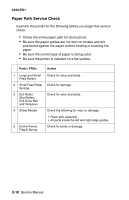
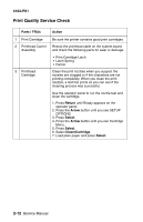
4102-P01 Operator Panel Button Service Check Parts / FRUs 1 Buttons System Board Action If the LCD display is OK, but the buttons do not function, run the "Button Test" on page 3-2. If any of the buttons fail, replace the top cover/ buttons/key PCB w/label assembly. If the symptom remains, replace the system board. LCD Assembly Display Service Check Parts / FRUs 1 LCD Assembly System Board Action If the LCD assembly is blank and the printer completes POST, check the system board cable connections. Check for a voltage reading of approximately +4 V dc on pin 15 at connector J631. If the voltage is correct, replace the LCD assembly. If the voltage is incorrect, replace the system board. If all diamonds are displayed after the printer completes POST, check the LCD assembly cable for continuity and replace the LCD assembly if necessary. Unplug power supply to the machine and replug. If diamonds remain, replace the system board. Run the "LCD Test," on page 3-2. If the test does not show all pels, replace the LCD assembly. Diagnostic Information 2-7
-
 1
1 -
2
-
3
-
4
-
5
-
6
-
7
-
8
-
9
-
10
-
11
-
12
-
13
-
14
-
15
-
16
-
17
-
 18
18 -
 19
19 -
 20
20 -
 21
21 -
 22
22 -
 23
23 -
 24
24 -
 25
25 -
 26
26 -
 27
27 -
 28
28 -
29
-
30
-
31
-
32
-
33
-
34
-
35
-
36
-
37
-
38
-
39
-
40
-
41
-
42
-
43
-
44
-
45
-
46
-
47
-
48
-
49
-
50
-
51
-
52
-
53
-
54
-
55
-
56
-
57
-
58
-
59
-
60
-
61
-
62
-
63
-
64
-
65
-
66
-
67
-
68
-
69
-
70
 |
 |
