LiftMaster 8365-267 8365-267 Owners Manual - Page 19
Power, Typical Wiring, Permanent Wiring
 |
View all LiftMaster 8365-267 manuals
Add to My Manuals
Save this manual to your list of manuals |
Page 19 highlights
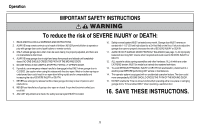
Power 1 Connect Power To prevent possible SERIOUS INJURY or DEATH from electrocution or fire: l Be sure power is NOT connected to the opener, and disconnect power to circuit BEFORE removing cover to establish permanent wiring connection. l Garage door installation and wiring MUST be in compliance with ALL local electrical and building codes. l NEVER use an extension cord, 2-wire adapter, or change plug in ANY way to make it fit outlet. Be sure the opener is grounded. To avoid installation difficulties, do not activate the garage door opener at this time. To reduce the risk of electric shock, your garage door opener has a grounding type plug with a third grounding pin. This plug will only fit into a grounding type outlet. If the plug doesn't fit into your outlet, contact a qualified electrician to install the proper outlet. THERE ARE TWO OPTIONS FOR CONNECTING POWER: OPTION A TYPICAL WIRING 1. Plug in the garage door opener into a grounded outlet. 2. DO NOT run garage door opener at this time. TYPICAL WIRING OPTION B PERMANENT WIRING If permanent wiring is required by your local code, refer to the following procedure. To make a permanent connection through the 7/8 inch hole in the top of the motor unit (according to local code): 1. Remove the motor unit cover screws and set the cover aside. 2. Remove the attached 3-prong cord. 3. Connect the black (line) wire to the screw on the brass terminal; the white (neutral) wire to the screw on the silver terminal; and the ground wire to the green ground screw. The opener must be grounded. 4. Reinstall the cover. PERMANENT WIRING Ground Tab Green Ground Screw Ground Wire White Wire Black Wire Black Wire 18
-
 1
1 -
2
-
3
-
4
-
5
-
6
-
7
-
8
-
9
-
10
-
11
-
12
-
13
-
 14
14 -
 15
15 -
 16
16 -
 17
17 -
 18
18 -
 19
19 -
 20
20 -
 21
21 -
 22
22 -
 23
23 -
 24
24 -
25
-
26
-
27
-
28
-
29
-
30
-
31
-
32
-
33
-
34
-
35
-
36
-
37
-
38
-
39
-
40
-
41
-
42
-
43
-
44
-
45
-
46
-
47
-
48
-
49
-
50
-
51
-
52
-
53
-
54
-
55
-
56
-
57
-
58
-
59
-
60
-
61
-
62
-
63
-
64
-
65
-
66
-
67
-
68
-
69
-
70
-
71
-
72
 |
 |
