LiftMaster SW425 SW425 Manual
LiftMaster SW425 Manual
 |
View all LiftMaster SW425 manuals
Add to My Manuals
Save this manual to your list of manuals |
LiftMaster SW425 manual content summary:
- LiftMaster SW425 | SW425 Manual - Page 1
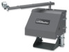
OWNER'S MANUAL MODEL SW425 RESIDENTIAL SWING GATE OPERATOR 2 YEAR WARRANTY Serial located on electrical box cover) Installation Date MODEL SW425 IS FOR USE ON VEHICULAR PASSAGE GATES ONLY AND IS NOT INTENDED FOR USE ON PEDESTRIAN PASSAGE GATES - LiftMaster SW425 | SW425 Manual - Page 2
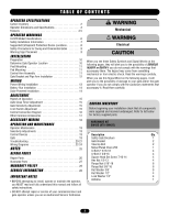
19 Gate 19 Troubleshooting 20- manual and follow all safety instructions. • DO NOT attempt repair or service of your commercial door and gate operator unless you are an Authorized Service parts. HARDWARE KIT SW425 (K7X-SW425) Description Qty. Safety Gate Brochure 1 Gate Bracket 2 Take - LiftMaster SW425 | SW425 Manual - Page 3
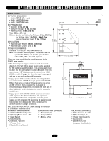
There are three possibilities for supplying power to the SW425 gate operator: • The standard power supply version is made remotely. Because the power is low 12Vdc, the wire can be direct burial wire which eliminates the need for expensive conduit runs. 20-3/4" (52.7 cm) • Supply power to the SW425 - LiftMaster SW425 | SW425 Manual - Page 4
solar panel is normally attached to the gate opener, it should be placed where the panel receives maximum sunlight. VISUAL FEEDBACK The SW425 Full Systems Capability circuit board is equipped with visual feedback LEDs to simplify installation and trouble-shooting. Located directly beside each input - LiftMaster SW425 | SW425 Manual - Page 5
only in addition to another open device connected to Open Input so the gate can still be opened if necessary. SAFETY INPUT: Normally open devices are connected to terminals 4 and 6 on the SW425 circuit board to cause the gate operator to open and/or hold the gate open in any position except the - LiftMaster SW425 | SW425 Manual - Page 6
servicing the general public, in which unauthorized access is prevented via supervision by security personnel. SAFETY ACCESSORY SELECTION All UL325 compliant LiftMaster gate for a control requiring continuous pressure to operate the operator open and close. Type E: Built-in audio alarm. Examples - LiftMaster SW425 | SW425 Manual - Page 7
Rollers • Vertical Posts • Photoelectric Sensors • Instructional and Precautionary Signage 4. Install the gate operator only when: a. The operator is appropriate for the construction and the usage class of the gate. b. All openings of a horizontal slide gate are guarded or screened from the bottom - LiftMaster SW425 | SW425 Manual - Page 8
SUGGESTED ENTRAPMENT PROTECTION DEVICE LOCATIONS GATE SYSTEM (MASTER/SECOND SWING GATE) STREET In(tSerarfueptyt ) Loop Secondary Gate Operator Photo eye for open cycle Photo eye for open cycle Photo eye for open cycle Primary Gate Operator Run twisted wire from loop to operator Seal Loops - LiftMaster SW425 | SW425 Manual - Page 9
entrapment protection devices to protect in BOTH the open and close gate cycles. • Locate entrapment protection devices to protect between moving gate and RIGID objects, such as posts. • A swinging gate shall NOT open into public access ways. Primary Arm Torque Wrench WARNING SIGN PLACEMENT - LiftMaster SW425 | SW425 Manual - Page 10
LOCATION Determine the location where the operator is to be installed permanently. First close the gate and make a mark on the ground below the gate at 36" (91 cm) from the hinge. Open the gate and again make a mark on the ground at 36" (91 cm) from the hinge. A line may then be drawn - LiftMaster SW425 | SW425 Manual - Page 11
time for the concrete to harden (Figure 5). Figure 5 PAD MOUNTING If there is no existing concrete pad, and the gate operator will be concrete pad mounted, use the illustration as a guide for locating and sizing the concrete pad (Figure 6). There should be at least 6" (15 cm) of depth into the - LiftMaster SW425 | SW425 Manual - Page 12
tighten the two bolts on the primary arm. Figure 10 Closed Swivel Joint 36" (91 cm) 19" (48 cm) Center of Gate Hinge Surface of Ground Figure 11 Swivel Joint Open The second arm is shipped in two pieces and must be assembled. Connect the two pipe arm together with the pipe - LiftMaster SW425 | SW425 Manual - Page 13
cleared and secured, at that time the unit may be returned to service. • Disconnecting power at the fuse box BEFORE proceeding. Operator MUST be hot, neutral and ground) from the power source, through the conduit and into the gate operator (Figure 2). It is easier to run these wires back out of the - LiftMaster SW425 | SW425 Manual - Page 14
of the weather. Be sure the battery has been properly charged before putting into operation. NOTE: Polarity must be correct. SOLAR POWERED INSTALLATION If the gate operator is solar powered, no power will need to be run into the machine. The ends of the wires are provided with connectors which can - LiftMaster SW425 | SW425 Manual - Page 15
after it has opened. To turn this feature on, flip the auto close timer to the on position (Figure 1). To adjust the amount of time it takes for the gate to begin closing use a small screw driver to turn the adjustment "pot" clockwise for more time (45 second maximum) or counter clockwise - LiftMaster SW425 | SW425 Manual - Page 16
servicing operator. 1 2 3 4 NOTES: Controls must be far enough from the gate so that the user is prevented from coming in contact with the gate , these open input terminals will cause the gate operator to open and will hold the gate open until the input is released and the hold open time has - LiftMaster SW425 | SW425 Manual - Page 17
operating the controls where the user has full view of gate operation. *We strongly recommend that you follow the UL guidelines presented throughout the manual. Installation device instructions: Always follow the instructions provided by the manufacturer when installing and adjusting any control - LiftMaster SW425 | SW425 Manual - Page 18
board must be OFF at all times. 1. Connect 115Vac to each SW425 gate operator. Connect the Master/Second wires (4) from the master circuit board 3). This optional timer can be adjusted to automatically close the gate after the gate has been open between 1 and 100 minutes. The extended timer will add - LiftMaster SW425 | SW425 Manual - Page 19
when the gate is not moving. 6. KEEP GATES PROPERLY MAINTAINED. Read the owner's manual. Have a qualified service person make repairs to gate hardware. 7. MUST be performed by a LiftMaster professional. 11. SAVE THESE INSTRUCTIONS. MAINTENANCE The SW425 is designed to be maintenance free - LiftMaster SW425 | SW425 Manual - Page 20
LEDS The SW425 Full Systems Capability circuit board has been equipped with Visual Feedback LEDs to simplify installation and troubleshooting. These are small lights which are located directly beside the input terminals. These LEDs give visual information to the installer or service technician - LiftMaster SW425 | SW425 Manual - Page 21
TROUBLESHOOTING GATE BEGINS TO OPEN OR CLOSE, THEN STOPS OR REVERSES • Adjust the gate sensitivity (page 15). If the gate sensitivity adjustment is too sensitive, the gate may stop in mid-travel or reverse. • It may be necessary to lubricate any mechanical parts on the gate such as wheels and clean - LiftMaster SW425 | SW425 Manual - Page 22
WIRING DIAGRAM - FULL SYSTEMS CAPABILIT Y, 115VAC WARNING 25 To protect against fire and electrocution: • DISCONNECT power BEFORE installing or servicing operator. See page 16 for Radio Wiring Specifications Radio Receiver 22 - LiftMaster SW425 | SW425 Manual - Page 23
WIRING DIAGRAM - FULL SYSTEMS CAPABILIT Y, BATTERY RUN WARNING To protect against fire and electrocution: • DISCONNECT power BEFORE installing or servicing operator. 25 See page 16 for Radio Wiring Specifications Radio Receiver 23 B R E A K E R 7 AMP - LiftMaster SW425 | SW425 Manual - Page 24
WIRING DIAGRAM - FULL SYSTEMS CAPABILIT Y, SOL AR POWERED WARNING To protect against fire and electrocution: 25 • DISCONNECT power BEFORE installing or servicing operator. See page 16 for Radio Wiring Specifications Radio Receiver B R E A K E R 7 AMP SOLAR PANEL 12VDC 5W 24 - LiftMaster SW425 | SW425 Manual - Page 25
NOTES 25 - LiftMaster SW425 | SW425 Manual - Page 26
32x1/2" and Flatwashers #6. I K75-40132 Primary and Secondary Arm Service Kit Complete with: Outer Primary Arm, Inner Primary Arm, Swivel 40083 29-40071 29-40089 29-40095 29-NP712 K79-40056 25-40152 DESCRIPTION Gate Bracket Motor, 12VDC Transformer, 120V 60HV Limit Switch, SPDT Overload 1.5 Amp - LiftMaster SW425 | SW425 Manual - Page 27
ILLUSTRATED PARTS I H 4 6 A 2 11 E D 3 B 10 C 1 F 8 G 7 5 9 27 - LiftMaster SW425 | SW425 Manual - Page 28
this product. Then send this product, pre-paid and insured, to our service center for warranty repair. You will be advised of shipping instructions when you call. Please include a brief description of the problem and a dated proof-of-purchase receipt with any product returned for warranty repair
-
 1
1 -
 2
2 -
 3
3 -
 4
4 -
 5
5 -
 6
6 -
 7
7 -
8
-
9
-
10
-
11
-
12
-
13
-
14
-
15
-
16
-
17
-
18
-
19
-
20
-
21
-
22
-
23
-
24
-
25
-
26
-
27
-
28
 |
 |

Serial #
________________________
(located on electrical box cover)
Installation Date __________________
2 YEAR WARRANTY
MODEL SW425 IS FOR USE ON VEHICULAR PASSAGE
GATES ONLY AND IS NOT INTENDED FOR USE ON
PEDESTRIAN PASSAGE GATES
OWNER’S MANUAL
MODEL SW425
RESIDENTIAL SWING GATE OPERATOR