LiftMaster SW425 SW425 Manual - Page 13
Wiring, Power Wiring Installation
 |
View all LiftMaster SW425 manuals
Add to My Manuals
Save this manual to your list of manuals |
Page 13 highlights
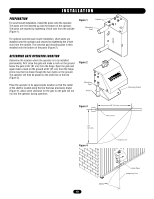
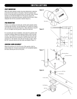
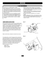
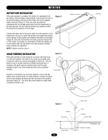
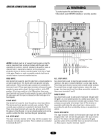
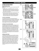
NING WWIARRI NNGING ION WARNING To reduce the risk of SEVERE INJURY or DEATH: • ANY maintenance to the operator or in the area near the operator MUST NOT be performed until disconnecting the electrical power and locking-out the power via the operator power switch. Upon completion of maintenance the area MUST be cleared and secured, at that time the unit may be returned to service. • Disconnecting power at the fuse box BEFORE proceeding. Operator MUST be properly grounded and connected in accordance with local electrical codes. NOTE: The operator should be on a separate fused line of adequate capacity. • ALL electrical connections MUST be made by a qualified individual. • DO NOT install any wiring or attempt to run the operator without consulting the wiring diagram. We recommend that you Install an optional reversing edge BEFORE proceeding with the control station installation. • ALL power wiring should be on a dedicated circuit and well protected. The location of the power disconnect should be visible and clearly labeled. • ALL power and control wiring MUST be run in separate conduit. • BEFORE installing power wiring or control stations be sure to follow all specifications and warnings described below. Failure to do so may result in SEVERE INJURY to persons and/or damage to operator. POWER WIRING INSTALLATION Before making any electrical connections be sure that the power is switched off. If the gate operator is a standard 115V model, run conduit from the 115V power source into the gate operator (Figure 1). The gate operator is provided with a 90 degree flexible conduit fitting for installations where the electrical box is relatively close. Because of the 90 degree fitting, it is generally easier to run the electrical wires through the flexible conduit before attaching the conduit. Wiring for other devices such as push buttons may also be run at this time either in the same conduit or in another. Figure 1 Junction Box Flexible Conduit Make sure that wiring is employed as required by local codes. If not already done, run three 12 gauge wires (hot, neutral and ground) from the power source, through the conduit and into the gate operator (Figure 2). It is easier to run these wires back out of the large hole in the operator along with the three existing wires. This allows the connection to be made externally and then later inserted back into the operator through the large hole. Be sure to use wire nuts to secure these connection. Be sure that the grounding wire is connected to a good earth ground. Make the connections as follows: • Black to (hot) • White to (neutral) • Green to (ground) Figure 2 Conduit Holes Conduit Fitting Line Neutral Ground Wire Nut 13
-
 1
1 -
2
-
3
-
4
-
5
-
6
-
7
-
 8
8 -
 9
9 -
 10
10 -
 11
11 -
 12
12 -
 13
13 -
 14
14 -
 15
15 -
 16
16 -
 17
17 -
 18
18 -
19
-
20
-
21
-
22
-
23
-
24
-
25
-
26
-
27
-
28
 |
 |
