LiftMaster SW425 SW425 Manual - Page 20
Troubleshooting, Gate Travels Too Far/not Far Enough
 |
View all LiftMaster SW425 manuals
Add to My Manuals
Save this manual to your list of manuals |
Page 20 highlights
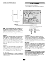
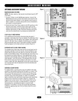
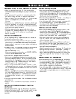
TROUBLESHOOTING EXPLANATION OF VISUAL FEEDBACK LEDS The SW425 Full Systems Capability circuit board has been equipped with Visual Feedback LEDs to simplify installation and troubleshooting. These are small lights which are located directly beside the input terminals. These LEDs give visual information to the installer or service technician indicating what commands are going into the circuit board from devices such as limit switches or from peripheral devices such as radio receivers or safety loops. There are also two LEDs which show output to the motor for both the opening and closing directions. REMOTE CONTROL DOES NOT WORK • Check the battery inside of the remote control and/or try another remote control. • Check to see which LEDs are illuminated on the circuit board. For normal operating conditions, the only LEDs that should be illuminated are the stop input at terminal 9 and Limit Switch 1 input if the gate is in the fully open position or Limit Switch 2 input if the gate is in the fully closed position. • If any of the input LEDs are illuminated on terminals 4, 5, 7 or 10, disconnect wire from that input terminal that is illuminated until the LED is extinguished to determine which input device may be stuck in an on condition. • If it is the radio receiver that appears to be stuck in an on condition, check all remote controls to see if any of them are stuck on. • Make sure that there is power (10 to 16Vdc) to the receiver on terminals 8 and 12 and make sure that the circuit breaker button is pressed in and that the motor fuse is not blown. • If a click is heard while the remote control is being pressed and there is no response from the operator, check all receiver connections (page 16). • If there is still no response, see GATE WILL NOT OPEN OR CLOSE on next page. GATE TRAVELS TOO FAR/NOT FAR ENOUGH • Adjust the gate sensitivity (page 15). If the gate sensitivity adjustment is too sensitive, the gate may stop in mid-travel. • It may be necessary to lubricate any mechanical parts on the gate such as wheels and clean the gate track of any debris. • Check the limit switch input LEDs on terminals 1 and 3 to see if either one is illuminated. If one of the limit switch input LEDs is illuminated and the gate has traveled too far or not far enough, this indicates that the limits of travel may need adjustment. Adjust the limits of travel (page 15). This adjustment may change slightly as the chain stretches due to normal wear and it may change dramatically if the limit plate is accidentally left not engaged with the limit nuts. • If the limit nut has traveled past a limit switch, check the limit switch and all limit switch connections (pages 22 or 23). • Watch the stop input LED on terminal 9 while the gate operator is running and see if the LED flickers or extinguishes. This may indicate a faulty stop input device or a poor connection between the stop input terminal 9 and common. • If the stop input LED on terminal 9 flickers or extinguishes, check all connections to the stop input device and/or replace the faulty device. 20 INPUT Limit Switch 1 Limit Switch 2 Safety Open Pulse Open Normally Closed Stop Close DESCRIPTION This LED indicates that one of the normally open limit switches is pressed in and the gate is in the open position. This LED indicates that one of the normally open limit switches is pressed in and the gate is in the closed position. This LED indicates that there is a closed contact between safety input terminal 4 and common. This LED indicates that there is a closed contact between open input terminal 5 and common This LED indicates that there is a closed contact between Pulse Open input terminal 7 and common. This LED also stays illuminated while the gate is opening. This LED indicates that there is a closed contact between stop input terminal 9 and common. Under normal operating conditions this LED must be in the on condition in order for the system to function. This LED indicates that there is a closed contact between close input terminal 10 and common. This LED also stays illuminated while the gate is closing.
-
 1
1 -
2
-
3
-
4
-
5
-
6
-
7
-
8
-
9
-
10
-
11
-
12
-
13
-
14
-
 15
15 -
 16
16 -
 17
17 -
 18
18 -
 19
19 -
 20
20 -
 21
21 -
 22
22 -
 23
23 -
 24
24 -
 25
25 -
26
-
27
-
28
 |
 |
