LiftMaster SW425 SW425 Manual - Page 12
Gate Bracket And Pipe Arm Installation,
 |
View all LiftMaster SW425 manuals
Add to My Manuals
Save this manual to your list of manuals |
Page 12 highlights
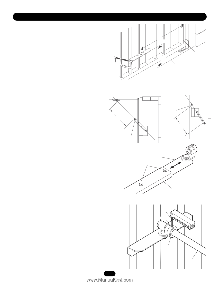
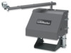
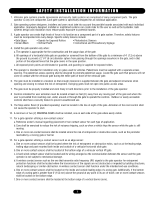
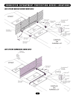
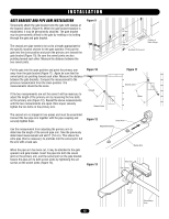
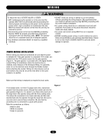
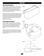
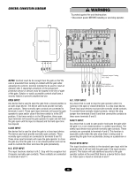
I N S TA L L AT I O N GATE BRACKET AND PIPE ARM INSTALLATION Temporarily attach the gate bracket onto the gate with clamps at the location shown (Figure 9). When the gate bracket location is established, it may be permanently attached. The gate bracket may be permanently affixed to the gate by welding or by bolting through the gate and gate bracket. Figure 9 The second arm pipe needs to be cut to a length appropriate for the specific location chosen for the gate operator. First put the gate into the close position and point the primary arm toward the gate bracket (Figure 10). Be sure the swivel joints are also pointing toward each other. Measure the distance between the two swivel joints. Put the gate into the open position and point the primary arm away from the gate bracket (Figure 11). Again be sure that the swivel joints are pointing toward each other. Measure the distance between the gate brackets. Compare the measurement to the previous measurement from the close position. The measurements should be the same. If the two measurements are not the same it will be necessary to adjust the length of the primary arm by loosening the two bolts on the primary arm (Figure 12). Repeat the above measurements until the two measurements are equal. Once equal, securely tighten the two bolts on the primary arm. Figure 10 Closed Swivel Joint 36" (91 cm) 19" (48 cm) Center of Gate Hinge Surface of Ground Figure 11 Swivel Joint Open The second arm is shipped in two pieces and must be assembled. Connect the two pipe arm together with the pipe coupling and securely tighten them. Use the measurement from adjusting the primary arm to determine the length of the second pipe arm. Take the previously determined measurement and add 3" (7.6 cm). This allows the extra pipe (that is necessary) to protrude into the swivel joint. Cut the arm with a hack saw. When the pipe arm has been cut, it may be attached to the gate operator and gate bracket. Insert the pipe into both the swivel joint on the primary arm, and the swivel joint on the gate bracket. Secure the pipe arm to both swivel joints by tightening the set screws on the swivel joints (Figure 13). Figure 12 Inner Arm Adjustment Bolt Figure 13 Outer Arm Hex Key Set Screw Swivel Joint Secondary Arm 12
-
 1
1 -
2
-
3
-
4
-
5
-
6
-
 7
7 -
 8
8 -
 9
9 -
 10
10 -
 11
11 -
 12
12 -
 13
13 -
 14
14 -
 15
15 -
 16
16 -
 17
17 -
18
-
19
-
20
-
21
-
22
-
23
-
24
-
25
-
26
-
27
-
28
 |
 |