LiftMaster SW425 SW425 Manual - Page 16
Control Connection Diagram, Open Input, Close Input, N.o. Stop Input, Safety Input, Pulse Open Input
 |
View all LiftMaster SW425 manuals
Add to My Manuals
Save this manual to your list of manuals |
Page 16 highlights
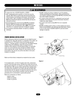
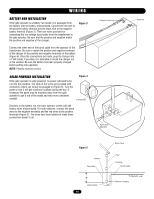
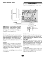
CONTROL CONNECTION DIAGRAM Radio Receiver WARNING To protect against fire and electrocution: CAUTION • Disconnect power BEFORE installing or servicing operator. 1 2 3 4 NOTES: Controls must be far enough from the gate so that the user is prevented from coming in contact with the gate while operating the controls. Controls intended to be used to reset an operator after 2 sequential activations of the entrapment protection device or devices must be located in the line of sight of the gate. Outdoor or easily accessible controls shall have a security feature to prevent unauthorized use. OPEN INPUT: Any device that is used to open the gate from a closed position is an open input device. The device used must provide normally open contacts. These normally open contacts are connected to terminals 5 and 6. These open input terminals will cause the gate operator to open and/or close if the timer switch is in the OFF position. If the timer switch is in the ON position, these open input terminals will cause the gate operator to open and will hold the gate open until the input is released and the hold open time has elapsed. CLOSE INPUT: Any device that is used to close the gate is a close input device. The device used must provide normally open contacts. These normally open contacts are connected to terminals 9 and 10. These close input terminals will cause the gate operator to close the gate any time the gate is in a non-closed position and can be used to override the timer and close the gate prematurely. N.O. STOP INPUT: This input functions identical to N.C. Stop with the exception that it requires normally open contacts. These contacts are connected to terminals 9 and 11. Remove jumper if using N.C. Stop Push buttons, key switches, etc. N.C. STOP INPUT: Any device that is used to stop the gate operator while it is running in the open or closed directions is a stop input device. These stop input devices must provide normally closed contacts. To connect these normally closed contacts, remove the stop jumper from terminals 8 and 9 and then connect the contacts to these same terminals 8 and 9. SAFETY INPUT: Any device that is used to open and/or hold open the gate while the gate is in a non-closed position is a safety input device. The safety input device must provide normally open contacts. These contacts are connected to terminals 4 and 6. This function is especially useful when the auto close timer is being used in preventing the gate from accidentally closing on a pedestrian or vehicle. PULSE OPEN INPUT: This input functions similarly to the standard open input with the exception that it will not hold the gate open if the input remains present. This feature will add additional security to the gate operator system in the event that there is a device that is stuck on. Pulse open is found at terminals 6 and 7. 16
-
 1
1 -
2
-
3
-
4
-
5
-
6
-
7
-
8
-
9
-
10
-
 11
11 -
 12
12 -
 13
13 -
 14
14 -
 15
15 -
 16
16 -
 17
17 -
 18
18 -
 19
19 -
 20
20 -
 21
21 -
22
-
23
-
24
-
25
-
26
-
27
-
28
 |
 |
