LiftMaster SW425 SW425 Manual - Page 5
Peripherals
 |
View all LiftMaster SW425 manuals
Add to My Manuals
Save this manual to your list of manuals |
Page 5 highlights
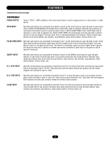
FEATURES continued from previous page PERIPHERALS POWER SUPPLY: There is 12Vdc .1 AMP available on the circuit board which is used to supply power to a radio receiver or other device. OPEN INPUT: Normally open devices are connected to terminals 5 and 6 on the circuit board to cause the gate to open and/or close in PUSH-TO-OPEN/PUSH-TO-CLOSE (Timer switch OFF) mode of operation. Normally open devices are connected to terminals 5 and 6 to cause the gate to open in AUTO CLOSE TIMER (Timer switch ON) mode of operation. In this mode of operation the AUTO CLOSE TIMER will automatically close the gate after a specific amount of time has elapsed. The Auto Close Timer is adjustable between 0-45 seconds. These normally open devices can be push buttons, key switches, loop detectors, photo electric beams, 24-hour timers, etc. PULSE OPEN INPUT: Normally open devices are connected to terminals 6 and 7 on the circuit board to cause the gate to open. Pulse Open Input functions identical to Open Input with the exception that it will not hold open the gate. If an open device is stuck on, the gate will still close. This feature is sometimes used to provide a higher level of security but should be used only in addition to another open device connected to Open Input so the gate can still be opened if necessary. SAFETY INPUT: Normally open devices are connected to terminals 4 and 6 on the SW425 circuit board to cause the gate operator to open and/or hold the gate open in any position except the fully closed position. Normally open safety input devices that can be used are push buttons, radio receivers, key switches, loop detectors, photo electric beams, 24-hour timers, etc. N.C. STOP INPUT: Normally closed devices are connected to terminals 8 and 9 on the circuit board after removing the stop jumper that is on terminals 8 and 9. The N.C. Stop Input will cause the gate to stop at any position and will remain stopped until activated to open or close. N.O. STOP INPUT: Normally open devices are connected to terminals 9 and 11 to cause the gate to stop in any position until the gate is again activated to open or close. N.O. Stop Input functions identical to N.C. Stop input with the exception that it requires normally open contacts instead of normally closed contacts. CLOSE INPUT: Normally open devices are connected to terminals 9 and 10 on the circuit board to cause the gate operator to close the gate when in any position. Normally open input devices that can be used are push buttons, radio receivers, key switches, loop detectors, photo electric beams, 24-hour timers, etc. 5
-
 1
1 -
 2
2 -
 3
3 -
 4
4 -
 5
5 -
 6
6 -
 7
7 -
 8
8 -
 9
9 -
 10
10 -
 11
11 -
12
-
13
-
14
-
15
-
16
-
17
-
18
-
19
-
20
-
21
-
22
-
23
-
24
-
25
-
26
-
27
-
28
 |
 |