LiftMaster SW425 SW425 Manual - Page 2

Table Of Contents, Carton Inventory

Page 2 highlights

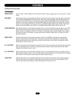
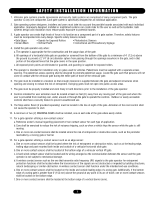
TABLE OF CONTENTS OPERATOR SPECIFICATIONS Carton Inventory 2 Operator Dimensions and Specifications 3 Features 4-5 WARNING OPERATOR WARNINGS UL325 Model Classifications 6 Safety Installation Information 7 Suggested Entrapment Protection Device Locations 8 CAUTION Safety Precautions for Swing and Ornamental Gates 9 Warning Sign Placement 9 INSTALLATION Preparation 10 Determine Gate Operator Location 10 Post Mounting 11 Pad Mounting 11 Control Arm Assembly 11 Gate Bracket and Pipe Arm Installation 12 WIRING Power Wiring Installation 13 Battery Run Installation 14 Solar Powered Installation 14 ADJUSTMENT Right/Left Operation 15 Auto Close Timer Adjustment 15 Gate Sensitivity Adjustment 15 Limit Switch Adjustment 15 Control Connection Diagram 16 Other Common Accessories 17 ACCESSORY WIRING 18 OPERATION AND MAINTENANCE Operator Maintenance 19 Sensitivity Adjustments 19 Control Devices 19 Gate 19 Troubleshooting 20-21 Wiring Diagrams 22-24 NOTES 25 REPAIR PARTS Repair Parts 26 Illustrated Parts 27 WARRANTY POLICY 28 SERVICE INFORMATION 28 IMPORTANT NOTES • BEFORE attempting to install, operate or maintain the operator, you MUST read and fully understand this manual and follow all safety instructions. • DO NOT attempt repair or service of your commercial door and gate operator unless you are an Authorized Service Technician. WARNING Mechanical CAUTION WARNING WARNING Electrical WARNING CAUTION When you see these Safety Symbols and Signal Words on the following pages, they will alert you to the possibility of SERIOUS INJURY or DEATH if you do not comply with the warnings that accompany them. The hazard may come from something mechanical or from electric shock. Read the warnings carefully. When you see this Signal Word on the following pages, it will alert you to the possibility of damage to your gate and/or the gate operator if you do not comply with the cautionary statements that accompany it. Read them carefully. CARTON INVENTORY Before beginning your installation check that all components were supplied and received undamaged. Refer to list below for factory supplied parts. HARDWARE KIT SW425 (K7X-SW425) Description Qty. Safety Gate Brochure 1 Gate Bracket 2 Take-Up Bolt 2 Nickel Plated Chain #50 1 U-Bolt 2" 5/16-18 4 U-Bolt 3" 3/8-16 4 Square Head Set Screw 7/16-14 4 Hex Nut 1/2-13 4 Flange Nut 5/16"-18 8 Flange Nut 3/8"-16 8 Flat Washer 3/8" 8 Flat Washer 1/2" 4 Lock Washer 1/2" 4 Antenna 1 2

  • 1
  • 2
  • 3
  • 4
  • 5
  • 6
  • 7
  • 8
  • 9
  • 10
  • 11
  • 12
  • 13
  • 14
  • 15
  • 16
  • 17
  • 18
  • 19
  • 20
  • 21
  • 22
  • 23
  • 24
  • 25
  • 26
  • 27
  • 28

2
CARTON INVENTORY
Before beginning your installation check that all components
were supplied and received undamaged. Refer to list below
for factory supplied parts.
Description
Qty.
Safety Gate Brochure
1
Gate Bracket
2
Take-Up Bolt
2
Nickel Plated Chain #50
1
U-Bolt 2" 5/16-18
4
U-Bolt 3" 3/8-16
4
Square Head Set Screw 7/16-14
4
Hex Nut 1/2-13
4
Flange Nut 5/16"-18
8
Flange Nut 3/8"-16
8
Flat Washer 3/8"
8
Flat Washer 1/2"
4
Lock Washer 1/2"
4
Antenna
1
HARDWARE KIT
SW425 (K7X-SW425)
IMPORTANT NOTES
• BEFORE attempting to install, operate or maintain the operator,
you MUST read and fully understand this manual and follow all
safety instructions.
• DO NOT attempt repair or service of your commercial door and
gate operator unless you are an Authorized Service Technician.
TABLE OF CONTENTS
OPERATOR SPECIFICATIONS
Carton Inventory . . . . . . . . . . . . . . . . . . . . . . . . . . . . . . . . . . . . .2
Operator Dimensions and Specifications . . . . . . . . . . . . . . . . . . .3
Features . . . . . . . . . . . . . . . . . . . . . . . . . . . . . . . . . . . . . . . . . .4-5
OPERATOR WARNINGS
UL325 Model Classifications . . . . . . . . . . . . . . . . . . . . . . . . . . . .6
Safety Installation Information
. . . . . . . . . . . . . . . . . . . . . . . . . .7
Suggested Entrapment Protection Device Locations . . . . . . . . . .8
Safety Precautions for Swing and Ornamental Gates
. . . . . . . . .9
Warning Sign Placement . . . . . . . . . . . . . . . . . . . . . . . . . . . . . . .9
INSTALLATION
Preparation
. . . . . . . . . . . . . . . . . . . . . . . . . . . . . . . . . . . . . . . .10
Determine Gate Operator Location
. . . . . . . . . . . . . . . . . . . . . .10
Post Mounting . . . . . . . . . . . . . . . . . . . . . . . . . . . . . . . . . . . . . .11
Pad Mounting
. . . . . . . . . . . . . . . . . . . . . . . . . . . . . . . . . . . . . .11
Control Arm Assembly
. . . . . . . . . . . . . . . . . . . . . . . . . . . . . . .11
Gate Bracket and Pipe Arm Installation . . . . . . . . . . . . . . . . . . .12
WIRING
Power Wiring Installation
. . . . . . . . . . . . . . . . . . . . . . . . . . . . .13
Battery Run Installation . . . . . . . . . . . . . . . . . . . . . . . . . . . . . . .14
Solar Powered Installation . . . . . . . . . . . . . . . . . . . . . . . . . . . . .14
ADJUSTMENT
Right/Left Operation
. . . . . . . . . . . . . . . . . . . . . . . . . . . . . . . . .15
Auto Close Timer Adjustment . . . . . . . . . . . . . . . . . . . . . . . . . .15
Gate Sensitivity Adjustment . . . . . . . . . . . . . . . . . . . . . . . . . . . .15
Limit Switch Adjustment . . . . . . . . . . . . . . . . . . . . . . . . . . . . . .15
Control Connection Diagram . . . . . . . . . . . . . . . . . . . . . . . . . . .16
Other Common Accessories
. . . . . . . . . . . . . . . . . . . . . . . . . . .17
ACCESSORY WIRING
. . . . . . . . . . . . . . . . . . . . . . . . . . . .18
OPERATION AND MAINTENANCE
Operator Maintenance . . . . . . . . . . . . . . . . . . . . . . . . . . . . . . . .19
Sensitivity Adjustments . . . . . . . . . . . . . . . . . . . . . . . . . . . . . . .19
Control Devices . . . . . . . . . . . . . . . . . . . . . . . . . . . . . . . . . . . . .19
Gate . . . . . . . . . . . . . . . . . . . . . . . . . . . . . . . . . . . . . . . . . . . . . .19
Troubleshooting . . . . . . . . . . . . . . . . . . . . . . . . . . . . . . . . . .20-21
Wiring Diagrams
. . . . . . . . . . . . . . . . . . . . . . . . . . . . . . . . .22-24
NOTES
. . . . . . . . . . . . . . . . . . . . . . . . . . . . . . . . . . . . . . . . . .25
REPAIR PARTS
Repair Parts . . . . . . . . . . . . . . . . . . . . . . . . . . . . . . . . . . . . . . . .26
Illustrated Parts . . . . . . . . . . . . . . . . . . . . . . . . . . . . . . . . . . . . .27
WARRANTY POLICY
. . . . . . . . . . . . . . . . . . . . . . . . . . . . . .28
SERVICE INFORMATION
. . . . . . . . . . . . . . . . . . . . . . . . . .28
When you see these Safety Symbols and Signal Words on the
following pages, they will alert you to the possibility of
SERIOUS
INJURY or DEATH
if you do not comply with the warnings that
accompany them. The hazard may come from something
mechanical or from electric shock. Read the warnings carefully.
When you see this Signal Word on the following pages, it will
alert you to the possibility of damage to your gate and/or the gate
operator if you do not comply with the cautionary statements that
accompany it. Read them carefully.
Mechanical
Electrical
CAUTION
WARNING
WARNING