Lowrance HDS-7 LIVE HDS Live Installation Manual - Page 27
Video input configuration, Sonar CH1 - blue 9-pin connector - transducer
 |
View all Lowrance HDS-7 LIVE manuals
Add to My Manuals
Save this manual to your list of manuals |
Page 27 highlights
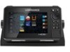
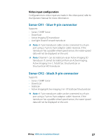
Video input configuration Configurations to video input are made in the video panel, refer to the Operator Manual for more information. Sonar CH1 - blue 9-pin connector Supports: • Sonar / CHIRP Sonar • DownScan • Active Imaging 3D transducer • LiveSight Down/Forward transducer Ú Note: A 7-pin transducer cable can be connected to a 9-pin port using a 7-pin to 9-pin adaptor cable. However, if the transducer has a paddle wheel speed sensor, the water-speed data will not be displayed on the unit. Ú Note: Channel 1 can do SideScan via an Active Imaging 3D transducer. It cannot do SideScan from an Active Imaging, Active Imaging 3-in-1, TotalSCan, StructureScan or StructureScan HD transducer. Sonar CH2 - black 9-pin connector Supports: • Sonar / CHIRP Sonar • DownScan • SideScan • Active Imaging/Active imaging 3-in-1/TotalScan/StructureScan Ú Note: A 7-pin transducer cable can be connected to a 9-pin port using a 7-pin to 9-pin adaptor cable. However, if the transducer has a paddle wheel speed sensor, the water-speed data will not be displayed on the unit. Wiring | HDS Live Installation Manual 27
-
 1
1 -
2
-
3
-
4
-
5
-
6
-
7
-
8
-
9
-
10
-
11
-
12
-
13
-
14
-
15
-
16
-
17
-
18
-
19
-
20
-
21
-
 22
22 -
 23
23 -
 24
24 -
 25
25 -
 26
26 -
 27
27 -
 28
28 -
 29
29 -
 30
30 -
 31
31 -
 32
32 -
33
-
34
-
35
-
36
-
37
-
38
-
39
-
40
-
41
-
42
-
43
-
44
-
45
-
46
-
47
-
48
-
49
-
50
-
51
-
52
-
53
-
54
-
55
-
56
-
57
-
58
-
59
-
60
-
61
-
62
-
63
-
64
-
65
-
66
-
67
-
68
-
69
-
70
 |
 |
