Lowrance HDS-7 LIVE HDS Live Installation Manual - Page 33
Adjust bearing alignment, Sidelobe suppression, beam by the radar antenna
 |
View all Lowrance HDS-7 LIVE manuals
Add to My Manuals
Save this manual to your list of manuals |
Page 33 highlights
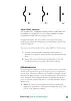
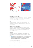
X X Adjust bearing alignment This option is used to align the heading marker on the screen with the center line of the vessel. This will compensate for any slight misalignment of the scanner during installation. Misalignment that is not corrected for will compromise target tracking and can result in dangerous misinterpretation of potential navigation hazards. Any inaccuracy will be evident when using MARPA or chart overlay. 1 Point the vessel towards a stationary isolated object, or towards a far range AIS where the AIS icon matches the radar echo 2 Adjust the coarse and fine bearing alignment so that the heading line touches the end of the selected object Sidelobe suppression Occasionally false target returns can occur adjacent to strong target returns such as large ships or container ports. This occurs because not all of the transmitted radar energy can be focused into a single beam by the radar antenna, a small amount energy is transmitted in other directions. This energy is referred to as sidelobe energy and occurs in all radar systems. The returns caused by sidelobes tend to appear as arcs. Ú Note: This control should only be adjusted by experienced radar users. Target loss in harbor environments may occur if this control is not adjusted correctly. Software setup | HDS Live Installation Manual 33
-
 1
1 -
2
-
3
-
4
-
5
-
6
-
7
-
8
-
9
-
10
-
11
-
12
-
13
-
14
-
15
-
16
-
17
-
18
-
19
-
20
-
21
-
22
-
23
-
24
-
25
-
26
-
27
-
 28
28 -
 29
29 -
 30
30 -
 31
31 -
 32
32 -
 33
33 -
 34
34 -
 35
35 -
 36
36 -
 37
37 -
 38
38 -
39
-
40
-
41
-
42
-
43
-
44
-
45
-
46
-
47
-
48
-
49
-
50
-
51
-
52
-
53
-
54
-
55
-
56
-
57
-
58
-
59
-
60
-
61
-
62
-
63
-
64
-
65
-
66
-
67
-
68
-
69
-
70
 |
 |
