MSI P55A User Guide - Page 64
CPU Amplitude Control/ PCIE Amplitude Control
 |
View all MSI P55A manuals
Add to My Manuals
Save this manual to your list of manuals |
Page 64 highlights
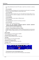
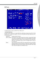
BIOS Setup This setting determines the time RFC takes to read from and write to a memory cell. ▶ CH1/ CH2 tWR Minimum time interval between end of write data burst and the start of a precharge command. Allows sense amplifiers to restore data to cells. ▶ CH1/ CH2 tWTR Minimum time interval between the end of write data burst and the start of a column-read command. It allows I/O gating to overdrive sense amplifiers before read command starts. ▶ CH1/ CH2 tRRD Specifies the active-to-active delay of different banks. ▶ CH1/ CH2 tRTP Time interval between a read and a precharge command. ▶ CH1/ CH2 tFAW This item is used to set the tFAW timing. ▶ Current CH1/ CH2 tdrRdTRd/ tddRdTRd/ tsrRdTWr/ tdrRdTWr/ tddRdTWr/ tsrWrTRd/ tddWrTWr/ tsrRDTRd/ tsrWrTWr These item show the advanced DRAM timings. ▶ Channel 1/ Channel2 Advanced Memory Setting Setting to [Auto] enables the advance memory timing automatically to be determined by BIOS. Setting to [Manual] allows you to set the following advanced memory timings. ▶ Memory Ratio This item allows you to set the memory multiplier. ▶ Adjusted DRAM Frequency (MHz) It shows the adjusted DRAM frequency. Read-only. ▶ QPI Ratio This item allows you to set the QPI multiplier. ▶ Adjusted QPI Frequency (MHz) It shows the adjusted QPI frequency. Read-only. ▶ ClockGen Tuner Press to enter the sub-menu and the following screen appears. ▶ CPU Amplitude Control/ PCIE Amplitude Control These items are used to select the CPU/ PCI Express clock amplitude. 3-24
-
 1
1 -
2
-
3
-
4
-
5
-
6
-
7
-
8
-
9
-
10
-
11
-
12
-
13
-
14
-
15
-
16
-
17
-
18
-
19
-
20
-
21
-
22
-
23
-
24
-
25
-
26
-
27
-
28
-
29
-
30
-
31
-
32
-
33
-
34
-
35
-
36
-
37
-
38
-
39
-
40
-
41
-
42
-
43
-
44
-
45
-
46
-
47
-
48
-
49
-
50
-
51
-
52
-
53
-
54
-
55
-
56
-
57
-
58
-
 59
59 -
 60
60 -
 61
61 -
 62
62 -
 63
63 -
 64
64 -
 65
65 -
 66
66 -
 67
67 -
 68
68 -
 69
69 -
70
-
71
-
72
-
73
-
74
-
75
-
76
-
77
-
78
-
79
-
80
-
81
-
82
-
83
-
84
-
85
-
86
-
87
-
88
-
89
-
90
-
91
-
92
-
93
-
94
-
95
-
96
-
97
-
98
-
99
-
100
-
101
-
102
 |
 |
