MSI P67A User Guide - Page 36
No Pin, Control pin, Control pin, Control pin, Ground, Control pin, Control pin, Control pin,
 |
View all MSI P67A manuals
Add to My Manuals
Save this manual to your list of manuals |
Page 36 highlights
Hardware Setup DLED3 Connector: JDLED3 (optional) This is reserved for connecting the msi future control card. 2.C4o.Cn6ot.rGn8otr.1lrCoo0puol1.inNnn2pdt1o.riC4noP.olCinnpotirnnotlropl in1p.i5n3V.C5So.BC7no.tCr9noo.tlGr1nop1rtl1roi.noR3pul.einnGpsdreinoruvendd pin Chassis Intrusion Connector: JCI1 This connector connects to the chassis intrusion switch cable. If the chassis is opened, the chassis intrusion mechanism will be activated. The system will record this status and show a warning message on the screen. To clear the warning, you must enter the BIOS utility and clear the record. 1.C2.IGNTroRuUnd 2-20
-
 1
1 -
2
-
3
-
4
-
5
-
6
-
7
-
8
-
9
-
10
-
11
-
12
-
13
-
14
-
15
-
16
-
17
-
18
-
19
-
20
-
21
-
22
-
23
-
24
-
25
-
26
-
27
-
28
-
29
-
30
-
 31
31 -
 32
32 -
 33
33 -
 34
34 -
 35
35 -
 36
36 -
 37
37 -
 38
38 -
 39
39 -
 40
40 -
 41
41 -
42
-
43
-
44
-
45
-
46
-
47
-
48
-
49
-
50
-
51
-
52
-
53
-
54
-
55
-
56
-
57
-
58
-
59
-
60
-
61
-
62
-
63
-
64
-
65
-
66
-
67
-
68
-
69
-
70
-
71
-
72
-
73
-
74
-
75
-
76
-
77
-
78
-
79
-
80
-
81
-
82
 |
 |
2-20
Hardware Setup
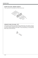
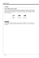
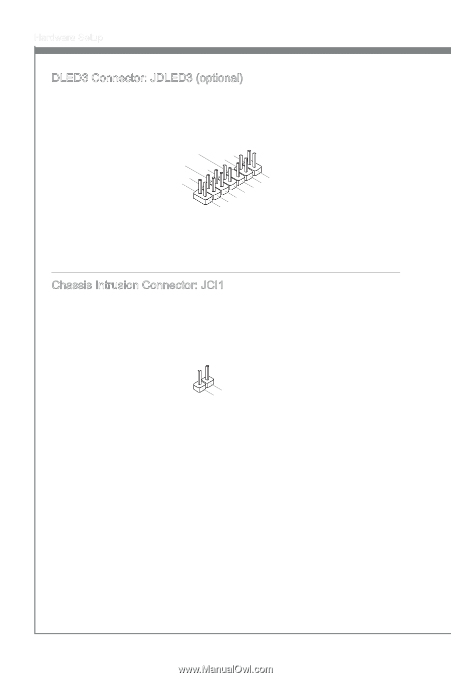
DLED3 Connector: JDLED3 (opt±onal)
Th±s ±s reserved for connect±ng the ms± future control card.
10.No Pin
14.Control pin
8.Control pin
12.Control pin
6.Ground
4.Control pin
2.Control pin
1.5VSB
3.Control pin
5.Control pin
7.Control pin
9.Ground
11.Reserved pin
13.Ground
Chass±s Intrus±on Connector: JCI1
Th±s connector connects to the chass±s ±ntrus±on sw±tch cable. If the chass±s ±s opened,
the chass±s ±ntrus±on mechan±sm w±ll be act±vated. The system w±ll record th±s status
and show a warn±ng message on the screen. To clear the warn±ng, you must enter the
BIOS ut±l±ty and clear the record.
1.CINTRU
2.Ground