Makita LS1219L LS1219L Instruction Manual - Page 23
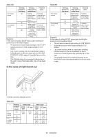
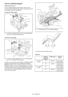
In the case of right bevel cut
 |
View all Makita LS1219L manuals
Add to My Manuals
Save this manual to your list of manuals |
Page 23 highlights
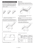
Table (B) - Molding Molding Finished position in edge against piece the figure guide fence For inside corner (a) Ceiling Finished contact edge piece will be should be on the Left against guide side of blade. fence. For outside corner (b) Wall contact (c) edge should be against guide fence. Finished piece will be on the Right (d) Ceiling side of blade. contact edge should be against guide fence. Example: In the case of cutting 52/38° type crown molding for position (a) in the above figure: • Tilt and secure bevel angle setting to 33.9° LEFT. • Adjust and secure miter angle setting to 31.6° RIGHT. • Lay crown molding with its broad back (hidden) surface down on the turn base with its CEILING CONTACT EDGE against the guide fence on the saw. • The finished piece to be used will always be on the LEFT side of the blade after the cut has been made. In the case of right bevel cut Table (B) - Molding Molding Finished position in edge against piece the figure guide fence For inside corner (a) Wall contact Finished edge should piece will be be against on the Right guide fence. side of blade. For outside corner (b) Ceiling (c) contact edge should be against guide fence. Finished piece will be on the Left side of blade. (d) Wall contact edge should be against guide fence. Example: In the case of cutting 52/38° type crown molding for position (a) in the above figure: • Tilt and secure bevel angle setting to 33.9° RIGHT. • Adjust and secure miter angle setting to 31.6° RIGHT. • Lay crown molding with its broad back (hidden) surface down on the turn base with its WALL CONTACT EDGE against the guide fence on the saw. • The finished piece to be used will always be on the RIGHT side of the blade after the cut has been made. (a) (b) 1 (c) (d) 2 1. Inside corner 2. Outside corner Table (A) - For inside corner For outside corner Molding position in the figure (a) (b) (c) (d) Bevel angle 52/38° 45° type type Right 33.9° Right 30° Miter angle 52/38° 45° type type Right 31.6° Left 31.6° Right 35.3° Left 35.3° Right 31.6° Right 35.3° 23 ENGLISH
-
 1
1 -
2
-
3
-
4
-
5
-
6
-
7
-
8
-
9
-
10
-
11
-
12
-
13
-
14
-
15
-
16
-
17
-
 18
18 -
 19
19 -
 20
20 -
 21
21 -
 22
22 -
 23
23 -
 24
24 -
 25
25 -
 26
26 -
 27
27 -
 28
28 -
29
-
30
-
31
-
32
-
33
-
34
-
35
-
36
-
37
-
38
-
39
-
40
-
41
-
42
-
43
-
44
-
45
-
46
-
47
-
48
-
49
-
50
-
51
-
52
-
53
-
54
-
55
-
56
-
57
-
58
-
59
-
60
-
61
-
62
-
63
-
64
-
65
-
66
-
67
-
68
-
69
-
70
-
71
-
72
-
73
-
74
-
75
-
76
-
77
-
78
-
79
-
80
-
81
-
82
-
83
-
84
-
85
-
86
-
87
-
88
-
89
-
90
-
91
-
92
-
93
-
94
-
95
-
96
-
97
-
98
-
99
-
100
-
101
-
102
-
103
-
104
 |
 |
