Maytag MED7500YW Use & Care Guide - Page 16
Direct Wire Connection
 |
View all Maytag MED7500YW manuals
Add to My Manuals
Save this manual to your list of manuals |
Page 16 highlights
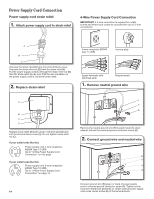
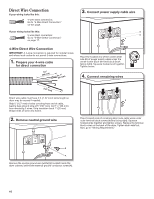
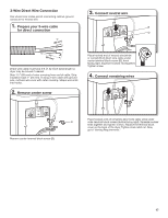
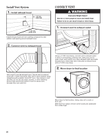
Direct Wire Connection If your wiring looks like this: 4-wire direct connection: Go to "4-Wire Direct Connection" on this page. If your wiring looks like this: 3-wire direct connection: Go to "3-Wire Direct Connection" on page 17. 3. Connect power supply cable wire B D 4-Wire Direct Wire Connection IMPORTANT: A 4-wire connection is required for mobile homes and where local codes do not permit 3-wire connections. 1. Prepare your 4-wire cable for direct connection 31 (89 ⁄2" mm) (251"mm) Place the hooked end of the center white wire (D) of power supply cable under the center screw (B) of terminal block (hook facing right). Squeeze hooked end together. Tighten screw. 4. Connect remaining wires (127 5" mm) Direct wire cable must have 5 ft. (1.52 m) of extra length so dryer may be moved if needed. Strip 5" (127 mm) of outer covering from end of cable, leaving bare ground wire at 5" (127 mm). Cut 11/2" (38 mm) from remaining 3 wires. Strip insulation back 1" (25 mm). Shape ends of wires into hooks. 2. Remove neutral ground wire F Place hooked ends of remaining direct wire cable wires under outer terminal block screws (hooks facing right). Squeeze hooked ends together and tighten screws. Replace the terminal block cover on the back of the dryer. Tighten strain relief nut. Now, go to "Venting Requirements." B A Remove the neutral ground wire (white) (F) located inside the dryer cabinet, behind the external ground conductor screw (A). 16
-
 1
1 -
2
-
3
-
4
-
5
-
6
-
7
-
8
-
9
-
10
-
 11
11 -
 12
12 -
 13
13 -
 14
14 -
 15
15 -
 16
16 -
 17
17 -
 18
18 -
 19
19 -
 20
20 -
 21
21 -
22
-
23
-
24
-
25
-
26
-
27
-
28
 |
 |
