McAfee IIP-M80K-ISAA User Guide - Page 10
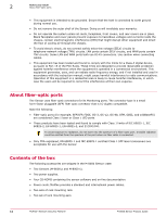
Four 10 Gigabit small form-factor pluggable XFP 10 Gigabit Interconnect ports - remote
 |
View all McAfee IIP-M80K-ISAA manuals
Add to My Manuals
Save this manual to your list of manuals |
Page 10 highlights
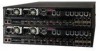
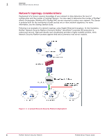
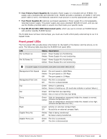
1 Overview M-8000 physical description Name Description 6 XFP Interconnect ports 7 Response port (on M-8000 S only) 8 Fail-Open Control ports 9 External Compact Flash port 10 Power Supply A 11 Power Supply B 12 10/100/1000 Interconnect ports 1 One RJ-45 10/100/1000 Management port on M-8000 P, which is used for communication with the Manager server. You can assign an IP address to this port during installation. 2 Two RS-232C Console ports, which you use to set up and configure the Sensor using the CLI of M-8000 P. You can use the Console port on the M-8000 S to recover the flash image. 3 Two RS-232C Auxiliary ports, which you might use to dial in remotely to set up and configure the Sensor. 4 Sixteen small form-factor pluggable (SFP) 1 Gigabit Monitoring ports, which enable you to monitor sixteen SPAN ports, eight full-duplex tapped segments, eight segments in-line, or a combination. For example, you can monitor four full-duplex segments and eight SPAN ports. These Monitoring interfaces of the M-8000 work in stealth mode, meaning they have no IP address and are not visible on the monitored segment. 5 Twelve 10 Gigabit small form-factor pluggable (XFP) 10 Gigabit Monitoring ports, which enable you to monitor twelve SPAN ports, six full-duplex tapped segments, six segments in-line, or a combination. For example, you can monitor three full-duplex segments and six SPAN ports. These Monitoring interfaces of the M-8000 work in stealth mode, meaning they have no IP address and are not visible on the monitored segment. If you choose to run in failover mode, ports 4A and 4B are used to interconnect with a standby M-8000 Sensor. The gigabit ports of the M-8000 running in in-line mode fail-close, meaning that if the Sensor fails, it will interrupt/block data flow. Fail-open functionality requires either the Layer 2 Passthru feature, described in detail in the Device Administration Guide, or the hardware Gigabit Fail-Open Bypass kit for gigabit ports, described in the Cable the failover interconnection ports section. 6 Four 10 Gigabit small form-factor pluggable (XFP) 10 Gigabit Interconnect ports, which enable you to connect the primary Sensor to the secondary Sensor. The Interconnect interfaces of the M-8000 work in stealth mode, meaning they have no IP address and are not visible on the monitored segment. 7 One RJ-45 Response port on M-8000 S, which, when you're operating in SPAN or tap mode, enables you to inject response packets back through a switch or router. 8 Fourteen RJ-11 Fail-Open Control ports, designed for use with the Optical Fail-Open Bypass kit. The ports are marked X1, X2, X3, X4, X5, X6, X7, X8, X9, X10, X11, X12, X13, and X14 and are used in conjunction with ports 1A/1B, 2A/2B, 3A/3B, 4A/4B, 5A/5B, 6A/6B, 7A/7B, 8A/8B, 9A/9B, 10A/10B, 11A/11B, 12A/12B, 13A/13B, and 14A/14B, respectively. 9 Two External Compact Flash ports. You use this only for flash recovery purposes. That is, use this port in troubleshooting situations where the Sensor's internal flash is corrupted, and you need to restart the Sensor through the external compact flash. For more information, search for the KnowledgeBase article at http://mysupport.mcafee.com/Eservice/. In the McAfee Technical Support ServicePortal page, click Search the KnowledgeBase. 10 McAfee® Network Security Platform M-8000 Sensor Product Guide
-
 1
1 -
2
-
3
-
4
-
 5
5 -
 6
6 -
 7
7 -
 8
8 -
 9
9 -
 10
10 -
 11
11 -
 12
12 -
 13
13 -
 14
14 -
 15
15 -
16
-
17
-
18
-
19
-
20
-
21
-
22
-
23
-
24
-
25
-
26
-
27
-
28
-
29
-
30
-
31
-
32
-
33
-
34
-
35
-
36
-
37
-
38
 |
 |