McAfee IIP-M80K-ISAA User Guide - Page 27
Connect the cables to the Interconnect ports, About connecting cables to the Monitoring ports - wiring
 |
View all McAfee IIP-M80K-ISAA manuals
Add to My Manuals
Save this manual to your list of manuals |
Page 27 highlights
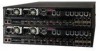
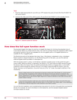
Attaching Cables to the Sensor Connect the cables to the Interconnect ports 4 Connect the cables to the Interconnect ports Communication between the M-8000 P and M-8000 S happens through the Interconnect ports. Task 1 Plug the supplied Ethernet cable into the XC1 port of the of M-8000 P. 2 Connect the other end of the Ethernet cable used in Step 1 into the XC4 port of M-8000 S. 3 Insert the supplied XFP modules into the XC2, XC3, XC5, and XC6 ports on M-8000 P and M-8000 S Sensors. Use only the modules supplied by McAfee or modules that you purchased from McAfee-approved vendors. 4 Plug one end of an LC-LC fiber-optic cable into the XC2 port of M-8000 P and connect the other end of the cable to the XC5 port of M-8000 S. 5 Plug one end of an LC-LC fiber-optic cable into the XC3 port of M-8000 P and connect the other end of the cable to the XC6 port of M-8000 S. About connecting cables to the Monitoring ports Connect to the network devices that you want to monitor through the Sensor monitoring ports. You can deploy Sensors in the following operating modes: • In-line mode (fail-close) • SPAN or hub mode • In-line mode (fail-open) • Failover • External tap mode How to use peer ports You must use two peer Monitoring ports of the Sensor to deploy it in a full-duplex mode. On the Sensor, the numbered ports are wired in pairs to accommodate the traffic. The following XFP 10 Gigabit Ethernet ports and SFP Gigabit Ethernet ports are coupled and must be used together: Port Pairs 1A and 1B 2A and 2B XC2 and XC3 3A and 3B 7A and 7B 8A and 8B 9A and 9B 10A and 10B 4A and 4B 5A and 5B Transceiver Type XFP XFP XFP XFP SFP SFP SFP SFP XFP XFP Sensor M-8000 P M-8000 P M-8000 P M-8000 P M-8000 P M-8000 P M-8000 P M-8000 P M-8000 S M-8000 S McAfee® Network Security Platform M-8000 Sensor Product Guide 27
-
 1
1 -
2
-
3
-
4
-
5
-
6
-
7
-
8
-
9
-
10
-
11
-
12
-
13
-
14
-
15
-
16
-
17
-
18
-
19
-
20
-
21
-
 22
22 -
 23
23 -
 24
24 -
 25
25 -
 26
26 -
 27
27 -
 28
28 -
 29
29 -
 30
30 -
 31
31 -
 32
32 -
33
-
34
-
35
-
36
-
37
-
38
 |
 |