Meade LX70 R5 5 inch Instruction Manual - Page 16
Alignment Collimation of, the Newtonian Reflector OTA
 |
View all Meade LX70 R5 5 inch manuals
Add to My Manuals
Save this manual to your list of manuals |
Page 16 highlights
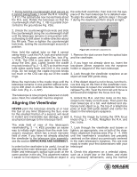
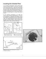
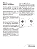
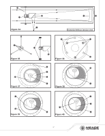
Alignment (Collimation) of the Newtonian Reflector OTA The optical systems of Newtonian Reflector telescopes include the following parts: primary mirror (Fig. 34, #1); secondary mirror (Fig. 34, #2); secondary mirror-holder (Fig. 34, #3); secondary mirror-vanes (Fig. 34, #4) and (Fig. 35, #1); primary mirror-tilt screws (Fig. 34, #5). The telescope's image is brought to a focus at (Fig. 34, #6). 1. Confirm alignment - To confirm optical alignment look down the focuser drawtube (Fig. 37, #1) with the eyepiece removed. The edge of the focuser drawtube frames reflections of the primary mirror (Fig. 37, #2), the secondary mirror (Fig. 37, #3), the four ("spider") vanes (Fig. 37, #4) holding the secondary mirror, and the observer's eye (Fig. 37, #5). With the optics properly aligned, all of these reflections appear concentric (centered), as shown in Fig. 37. Any deviation from concentricity of any of these telescope parts with the eye requires adjustments to the secondary mirror-holder (Fig. 35) and/or the primary mirror cell (Fig. 36), as described below. 2. Secondary mirror-vane adjustments: If the secondary mirror (1, Fig. 38) is left or right of center within the drawtube (Fig. 38, #2), slightly loosen the 3 collimation screws on the top of the secondary mirror holder (Fig. 35, #2). Next, tighten or loosen as necessary, the central Phillips screw to center the secondary mirror position in the focuser draw tube. When correctly positioned, lightly tighten the 3 collimation screws (Fig. 35, #2) until they touch the top of the secondary mirror. The secondary mirror should now be centered in the focuser drawtube left or right. If the secondary mirror (Fig. 38, #1) is above- or below-center within the drawtube, thread inward one of the adjustment/lock knobs (Fig. 35, #1) while unthreading another of these knobs. Only make adjustments to two knobs at a time until the secondary mirror appears as in Fig. 39. 3. Secondary mirror-holder adjustments: If the secondary mirror (Fig. 39, #1) is centered in the focuser drawtube (Fig. 39, #2), but the primary mirror is only partially visible in the reflection (Fig. 39, #3), the three secondary mirror collimation screws (Fig. 35, #2) should be slight- ly unthreaded to the point where the secondary mirror-holder (Fig. 35, #3) can rotate about its axis parallel to the main tube. Grasp the secondary mirror-holder (avoid touching the mirror surface!) with your hand and rotate it until, looking through the drawtube, you can see the primary mirror centered as well as possible in the reflection of the secondary mirror. With the rotation of the secondary mirror-holder at this best-possible position, thread in the three secondary collimation screws (Fig. 35, #2) to lock the rotational position. Then, if necessary, make adjustments to these three collimation screws to refine the tilt-angle of the secondary mirror, until the entire primary mirror can be seen centered within the secondary mirror's reflection. With the secondary mirror thus aligned the image through the drawtube appears as in Fig. 40. 4. Primary mirror adjustments: If the secondary mirror (Fig. 40, #1) and the reflection of the primary mirror (Fig. 40, #2) appear centered within the drawtube (Fig. 40, #3), but the reflection of your eye and the reflection of the secondary mirror (Fig. 40, #4) appear off-center, then the primary mirror tilt requires adjusting, using the Phillips head screws of the primary mirror cell (Fig. 36, #3). These primary mirror-tilt screws are located behind the primary mirror, at the lower end of the main tube. See Fig. 36. Before adjusting the primary mirror-tilt screws, first unscrew by several turns the three long primary mirror lock screws (Fig. 36, #2) which are also located on the rear surface of the primary mirror cell and which alternate around the cell's circumference with the three long and thin thumbscrews. These lock screws do not have springs beneath them. Then by trial and error turn the primary mirror tilt thumbscrews (Fig. 36, #3) until you develop a feel for which way to turn each screw to center the reflection of your eye in the drawtube. (An assistant is helpful in this operation.) With your eye centered as shown in Fig. 37, turn the three long and thin mirror lock screws (Fig. 36, #2) to re-lock the tilt-angle of the primary mirror. 5. The telescope's optical system is now aligned, or collimated. This collimation should be rechecked from time to time, with small adjustments (per steps 1, 2, and/or 3, above) effected as required to keep the optics well-aligned. 16
-
 1
1 -
2
-
3
-
4
-
5
-
6
-
7
-
8
-
9
-
10
-
 11
11 -
 12
12 -
 13
13 -
 14
14 -
 15
15 -
 16
16 -
 17
17 -
 18
18 -
 19
19 -
 20
20 -
 21
21 -
22
-
23
-
24
-
25
-
26
-
27
-
28
 |
 |