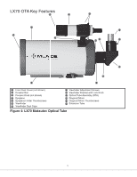
Meade LX70 R5 5 inch Instruction Manual - Page 7
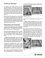
Getting Started
 |
View all Meade LX70 R5 5 inch manuals
Add to My Manuals
Save this manual to your list of manuals |
Page 7 highlights
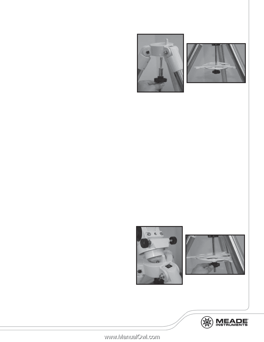
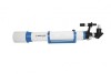
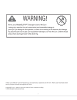
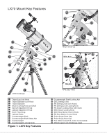
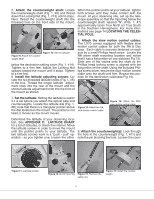
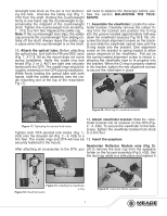
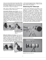
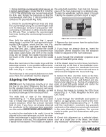
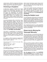
Getting Started shaft with the flat side facing up. Loosely thread on the Tripod Spreader Lock Knob and washer The Meade LX70 series models are versatile, high-resolution telescopes. They offer unmatched mechanical and optical performance that reveal nature in an ever-expanding level of detail. Observe the feather structure of an eagle from 50 yards or study the rings of the planet Saturn from a distance of 800 million miles. Focus beyond the Solar System and observe majestic nebulae, ancient star clusters, and remote galaxies. Figure 6: Tripod spreader Meade LX70 series telescopes are instruments Figure 5: Installing the fully capable of growing with your interest and mount locking knob and shaft can meet the requirements of the most demand- ing advanced observer. Before using your tele- to prevent the tripod spreader from falling off the scope, read the entire instructions carefully. Your shaft. telescope should be assembled during daylight hours and setup in an area that allows you to 4. Attach mount to tripod: Place the LX70 unpack all the included parts. mount onto the tripod head with the protrusion on top of the tripod's head positioned between Unpacking and Assembly the fine azimuth adjustment knobs (Fig 1, #5 ). If necessary, back off the azimuth adjustment knobs wide enough for the protrusion to fit be- 1. Remove the components from the boxes: tween them. Remove and identify the telescope's equipment. Refer to FIG. 1 - 4 for images of the parts and Next, tighten the Mount Locking Knob (Fig. 1, the overall assembly of your telescope. #4) so the mount secures to the tripod head. Tighten this knob to a firm feel. Then rotate the When removing the tripod from the box, hold the Tripod Spreader (Fig. 1, #3) so the wings of the assembly parallel (horizontal) to the ground or spreader align with each tripod leg. Tighten the the inner tripod leg extensions may slide out if Tripod Spreader Lock Knob(Fig. 1, #2) until firm. they are not locked in place. Tighten the tripod When you wish to collapse the tripod, loosen leg lock knobs (Fig. 1. #1) to secure the legs in the Tripod Spreader Lock Knob and rotate the place. wings so they are between the tripod legs. You do not need to remove the Tripod Spreader un- 2. Adjust the tripod legs: Spread the tripod less desired. legs as far apart as they will open. Now adjust the individual tripod legs by loosening the tripod leg lock knobs and extending the inner legs un- til the tripod head is approximately level to the ground. Relock the leg lock knob until firm. 3. Attach the spreader bar to the tripod: Thread the small end of the Mount Locking Knob and Shaft (Fig. 1, #4) along with the washer all the way into the bottom of the tripod head. When complete, the shaft will be held captive and allowed to be raised above the threads. Next, remove the Tripod Spreader Lock Knob (Fig. 1, #2) and washer. Place the center hole of the Tripod Spreader (Fig. 1, #3) onto the chrome Figure 7: Attaching mount to tripod Figure 8: Tightening the spreader lock knob 7
-
 1
1 -
 2
2 -
 3
3 -
 4
4 -
 5
5 -
 6
6 -
 7
7 -
 8
8 -
 9
9 -
 10
10 -
 11
11 -
 12
12 -
13
-
14
-
15
-
16
-
17
-
18
-
19
-
20
-
21
-
22
-
23
-
24
-
25
-
26
-
27
-
28
 |
 |