Meade LX850-ACF 10 inch User Manual - Page 15
Attach the Counterweight Shaft, Attach the Counterweights, Routing Connector Cables Internally
 |
View all Meade LX850-ACF 10 inch manuals
Add to My Manuals
Save this manual to your list of manuals |
Page 15 highlights
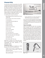
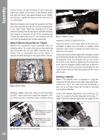
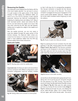
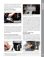
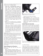
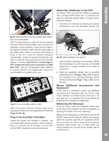
Assembly latitude scale has markings and a range that start at zero (0) and ends at 70. Turn the Attitude Adjustment Knob until the indicator points to your corresponding latitude. Tighten the Attitude Adjustment Lock Knob. Attach the Counterweight Shaft Remove the counterweight shaft, with attached safety nut, from its packaging. The safety nut is attached at the factory for shipping. Removing the safety nut at this time to lighten the counterweight shaft and make it easier to attach on the DEC axis. Remove the retaining nut by unscrewing it and set aside. Thread the shaft into the receiver, making sure that the threads are matching, not binding or cross threading. Attach the Counterweight(s) The counterweights are attached by threading them onto the counterweight shaft to the desired position. If the LX850 mount was purchased with a Meade optical tube assembly (OTA), additional counterweights may have been included depending on the OTA purchased. Attach all counterweights that were included with the mount. A good starting position for the counterweights is to place them in the middle portion of the counterweight THE POSITION OF YOUR HANDS SO NOT TO PINCH THEM DURING ADJUSTMENT. Screw the safety nut on then end of the shaft after the counterweight(s) have been attached. Routing Connector Cables Internally Designed into the LX850 mount is a raceway that routes cables through the body of the mount. Cables connecting the RA, DEC motors and StarLock to the control panel can be routed through this raceway, eliminating worrisome "cable interference." The dedicated connecting cable(s) can be found in the StarLock and/or the accessories box along with a assisting cable routing tool. Cables for additional equipment such as cameras can also be routed through the internal raceway. Note: the StarLock cable has been installed at the factory. Starlock's 6-pin Remove these four fasteners to gain access to dovetail saddle plate fasteners. Fig 13: Attach Counterweight. Fig 14: Remove left OTA dove tail mount. connector connects to the control panel and the 4-pin connector should be threaded through the hole in the saddle plate and connected to the StarLock. shaft. When the mount is fully assembled with OTA and accessories, the counterweights will be adjusted to obtain a proper balance with the OTA. Note: 12" and 14" f/8 ACF models please refer to Appendix F for detailed counterweight instructions. NOTE: WHEN ATTACHING THE COUNTERWEIGHT(S) TAKE CARE NOT TO DROP THEM DURING ASSEMBLY AS THEY CAN CAUSE SERIOUS INJURY, ESPECIALLY ON THE FOOT. WHEN ATTACHING OR ADJUSTING THE POSITION OF TWO (2) Counterweights PAY ATTENTION TO Remove these fasteners to remove dovetail saddle plate. Fig 15: Access to left saddle fastener revealed. 15
-
 1
1 -
2
-
3
-
4
-
5
-
6
-
7
-
8
-
9
-
 10
10 -
 11
11 -
 12
12 -
 13
13 -
 14
14 -
 15
15 -
 16
16 -
 17
17 -
 18
18 -
 19
19 -
 20
20 -
21
-
22
-
23
-
24
-
25
-
26
-
27
-
28
-
29
-
30
-
31
-
32
-
33
-
34
-
35
-
36
-
37
-
38
-
39
-
40
-
41
-
42
-
43
-
44
-
45
-
46
-
47
-
48
-
49
-
50
-
51
-
52
-
53
-
54
-
55
-
56
-
57
-
58
-
59
-
60
 |
 |
