Meade LX850-ACF 10 inch User Manual - Page 16
Removing the Saddle, StarLock Cable
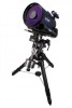 |
View all Meade LX850-ACF 10 inch manuals
Add to My Manuals
Save this manual to your list of manuals |
Page 16 highlights
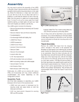
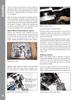
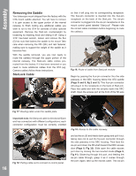
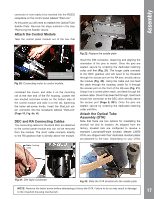
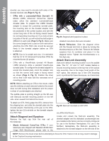
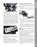
AutoStar #497 HAsAsNeDmBbOlyX Removing the Saddle Your telescope mount shipped from the factory with the OTA mount saddle attached. You will have to remove it to gain access to the upper portion of the internal raceway to finish routing any additional cables you want to run to the OTA for cameras of other optional equipment. Remove the StarLock counterweight by loosening its retaining knob and sliding it off. Using a 3/16" hex-head wrench, loosen and remove the five (5) hex nuts that fastens the saddle to the mount Take care when removing the fifth (5th) and last fastener; making sure to support the weight of the saddle as it becomes free. With the saddle removed, you are now ready to route the cable(s) through the upper portion of the internal raceway. The StarLock cable comes prerouted from the factory. If it has been removed or you need to route additional cables from the OTA (eg. Camera cables) follow these instructions. StarLock Cable: so that it will plug into its corresponding receptacle. The four-pin connector is inserted into the four-pin receptacle on the back of the StarLock. The six-pin connector is plugged into the six-pin receptacle on the mount control panel labeled "StarLock". Please note the correct cable orientation before beginning to route the cable(s). Fig 19: Route of cable from StarLock module Begin by passing the four-pin connector thru the side passway in the DEC housing below the OTA saddle (Page 8 and 9, fig 2 and 3). This four-pin connector will plug-in to the receptacle on the back of StarLock. Pass the cable end with the six-pins down the DEC shaft. Open the access port at the front of the RA axis Direction of Cable Fig 17: Routing cable under the saddle plate. Important note: the StarLock cable is directional! Each end has connectors with different configurations; each connector configuration must be correctly oriented Fig 16: Access to the cable raceway. Fig 18: Pulling cable out to connect to control panel. 16 and as the six (6) end feeds down grasp and pull it out, taking care not to pull the four-pin connector through the side passway in the DEC housing. Then feed the six-pin end down the RA shaft toward the DEC access door (Page 8, Fig 32). Slide open the cable access port door by loosing the two knurled knobs (Page 9, Fig 41). Observing through this port, and feeding the six-pin cable through, grasp it as it comes through the port. Again, take up the excess cable. This six-pin
-
 1
1 -
2
-
3
-
4
-
5
-
6
-
7
-
8
-
9
-
10
-
 11
11 -
 12
12 -
 13
13 -
 14
14 -
 15
15 -
 16
16 -
 17
17 -
 18
18 -
 19
19 -
 20
20 -
 21
21 -
22
-
23
-
24
-
25
-
26
-
27
-
28
-
29
-
30
-
31
-
32
-
33
-
34
-
35
-
36
-
37
-
38
-
39
-
40
-
41
-
42
-
43
-
44
-
45
-
46
-
47
-
48
-
49
-
50
-
51
-
52
-
53
-
54
-
55
-
56
-
57
-
58
-
59
-
60
 |
 |
