NEC MD322C8 Users Manual - Page 36
White Point Matching/Copy
 |
View all NEC MD322C8 manuals
Add to My Manuals
Save this manual to your list of manuals |
Page 36 highlights
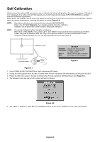
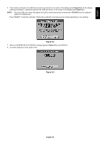
White Point Matching/Copy The white point can be copied from one display to one or more additional displays. Using this feature reduces the variation between different displays allowing them to match each other more closely. White Point Matching/Copy does not compensate for a typical yellow color shift due to long-term LCD usage. If this yellow shift is noticeable, please do Self Calibration. See page 32. NOTE: Stand-alone calibration can only be performed using the MDSVSENSOR3. Refer to the KEY MAP (Figure A) when changing settings during the calibration. Calibration can be performed in either portrait or landscape orientation. NOTE: You can start calibration without computer as following. When there is "NO SIGNAL" menu, press "LEFT", then "RIGHT" button and hold down simultaneously. All White Pattern Image will be displayed. After this, Plug-in the USB color sensor to the side (or bottom when Portrait orientation) USB downstream port. You can start Copy from step number 4. USB color sensor USB downstream USB icon is on the other side Figure C.1 Figure C.2 Display A - SOURCE display of white point to copy. Display B - MD322C8 which performs a copy. 1. Set the target white color on Display A. For example, change the wallpaper to a plain white background or use an application to display a white screen such as the editing screen of a word processor. 2. Using "LEFT" or "RIGHT" of Display B, select COPY in the MODE selection (Figure C.3). 3. Select the PICTURE MODE of Display B. 4. The procedure will ask for the USB color sensor to be placed on the center of the display panel (Figure C.4). Tilt the display panel approximately 5° backward and place the USB color sensor in the center of the display panel (Figure C.1). NOTE: Place the USB color sensor flat against the display to avoid external light contamination. Do not press the USB color sensor against the display panel. Press "SELECT". 5. Press SELECT on Display B to start measuring the white point of Display A. 6. After copying Display A information, the target luminance will be stored and displayed in the OSD of Display B. The white points of Display A and Display B should match. Press SELECT if the copy result is satisfactory. If the copy result is unsatisfactory, press "RESET". 7. When you want to confirm the white point of Display B, remove USB color sensor from source Display A and place in the center of Display B (Figure C.2). To skip the white point confirmation, Display B, press "SELECT" to step 9 for FINE TUNING. Figure C.3 Figure C.4 English-34 Figure C.5
-
 1
1 -
2
-
3
-
4
-
5
-
6
-
7
-
8
-
9
-
10
-
11
-
12
-
13
-
14
-
15
-
16
-
17
-
18
-
19
-
20
-
21
-
22
-
23
-
24
-
25
-
26
-
27
-
28
-
29
-
30
-
 31
31 -
 32
32 -
 33
33 -
 34
34 -
 35
35 -
 36
36 -
 37
37 -
 38
38
 |
 |
