NEC PX-50XM6A 42XM5/50XM6/60XM5 UM - Page 36
PLE LINK settings, IMAGE ADJUST settings, AUTO ID settings, P. ON DELAY settings
 |
View all NEC PX-50XM6A manuals
Add to My Manuals
Save this manual to your list of manuals |
Page 36 highlights
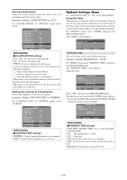
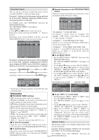
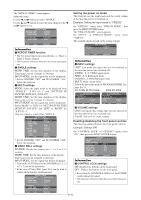
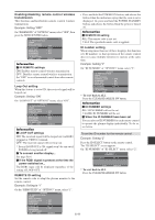
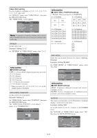
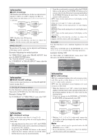
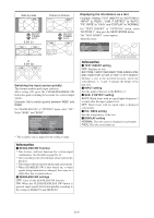
Information Ⅵ AUTO ID settings ON: Enables Auto ID function. In the case shown below, display 1 will be set as ID 1, display 2 as ID2, etc. This can be set only when a 2ן2, 3ן3, 1ן5 or 5ן1 is selected. REMOTE IN No.1 No.2 No.4 No.3 Display 1 REMOTE OUT REMOTE IN No.1 No.2 No.4 No.3 Display 2 REMOTE OUT REMOTE OUT No.1 No.2 No.4 No.3 Display 4 REMOTE OUT REMOTE IN No.1 No.2 No.4 No.3 REMOTE IN Display 3 OFF: Disables Auto ID function. Note: To use this function, you have to connect the displays with the remote cable (not supplied). * From the second monitor onward, neither the POWER button on the unit nor the POWER ON button on the remote control works. However, by pressing and holding the POWER ON button for more than 3 seconds, the monitor will be turned on. OFF: Turns on the main power of all displays at the same time. (Only for 4ן4 and 5ן5 video wall modes) MODE1: Turns on the main power of each display delayed. MODE2: Turns on the main power of each display more delayed. OFF: Turns on the main power of all displays at the same time. Note: To use this function, you have to connect the displays with the remote cable (not supplied). PLE LINK IMAGE ADJUST The position of the image can be adjusted and flickering of the image can be corrected. Example: Adjusting the vertical position Use this function to set a uniform brightness for each display. Turn on the AUTO ID and set the DIVIDER (at 1, 2ן2, 3ן3, 1ן5 or 5ן1) before the following operations. Example: Setting "ON" On "VIDEO WALL" menu, select "IMAGE ADJUST", then press the MENU/ENTER button. The "IMAGE ADJUST" screen appears. On "V-POSITION" of "IMAGE ADJUST" menu, adjust the position. IMAGE ADJUST ASPECT MODE : NORMAL V- P O S I T I O N H-POSITION V- H E I G H T H-WIDTH AUTO PICTURE : OFF FINE PICTURE PICTURE ADJ. UNDERSCAN : OFF SEL. ADJ. EXIT RETURN : ±0 : ±0 : 0 : 0 : 0 : 0 V-POSITION : +64 On "PLE LINK" of "VIDEO WALL" menu, select "ON", then press the MENU/ENTER button. VIDEO WALL DIVIDER : 1 POSITION DISP. MODE : SPLIT AUTO ID : OFF IMAGE ADJUST P. ON DELAY : OFF PLE LINK : ON SEL. ADJ. EXIT RETURN Information Information Ⅵ IMAGE ADJUST settings These are the same functions as the IMAGE ADJUST menu on page En-23. Ⅵ PLE LINK settings ON: Sets a uniform brightness for each screen in a video wall. This can be set only when a 1, 2ן2, 3ן3, 1ן5 or 5ן1 video wall is selected. OFF: Sets the individual screen brightness for each P. ON DELAY (Power on delay) Use this function to activate power-on delay. Turn on the AUTO ID before the following operations. Example: Setting "ON" screen in a video wall. * When this function is set "ON", connect your plasma displays with the remote cable (optional) in the order of the position numbers for the 2ן2 video wall. See the drawing below. On "P. ON DELAY" of "VIDEO WALL" menu, select "ON". VIDEO WALL DIVIDER : 1 POSITION DISP. MODE : SPLIT AUTO ID : OFF IMAGE ADJUST P. ON DELAY : ON PLE LINK : OFF * If there are changes in the DIVIDER or POSITION, the PLE LINK will automatically turn OFF. REMOTE IN No.1 No.2 No.4 No.3 Display 1 REMOTE OUT REMOTE IN No.1 No.2 No.4 No.3 Display 2 REMOTE OUT SEL. ADJ. EXIT RETURN Information Ⅵ P. ON DELAY settings REMOTE OUT No.1 No.2 No.4 No.3 Display 4 REMOTE OUT REMOTE IN No.1 No.2 No.4 No.3 REMOTE IN Display 3 (Video wall modes other than 4ן4 and 5ן5) * With the 3ן3, 1ן5 or 5ן1 video wall, connect the ON: Turns on the main power of each display after a delay time. final display to the first display the same way as with 2ן2 video wall. * Once this function has been set to "ON", the POWER Note: ON/OFF button on the remote control does not function * The remote control can be operated unless the IR except for the No.1 monitor. REMOTE is set to "OFF". By pressing the POWER ON button on the remote * To use this function, you have to connect the displays control the No.1 monitor will turn on and the others with the remote cable (not supplied). will be turned on one by one automatically. En-35
-
 1
1 -
2
-
3
-
4
-
5
-
6
-
7
-
8
-
9
-
10
-
11
-
12
-
13
-
14
-
15
-
16
-
17
-
18
-
19
-
20
-
21
-
22
-
23
-
24
-
25
-
26
-
27
-
28
-
29
-
30
-
 31
31 -
 32
32 -
 33
33 -
 34
34 -
 35
35 -
 36
36 -
 37
37 -
 38
38 -
 39
39 -
 40
40 -
 41
41 -
42
-
43
-
44
-
45
-
46
-
47
-
48
-
49
-
50
-
51
-
52
-
53
-
54
-
55
-
56
-
57
-
58
-
59
-
60
-
61
-
62
-
63
-
64
-
65
-
66
-
67
-
68
-
69
-
70
-
71
-
72
-
73
-
74
-
75
-
76
-
77
-
78
-
79
-
80
-
81
-
82
-
83
-
84
-
85
-
86
-
87
-
88
-
89
-
90
-
91
-
92
-
93
-
94
-
95
-
96
-
97
-
98
-
99
-
100
-
101
-
102
-
103
-
104
-
105
-
106
-
107
-
108
-
109
-
110
-
111
-
112
-
113
-
114
-
115
-
116
-
117
-
118
-
119
-
120
-
121
-
122
-
123
-
124
-
125
-
126
-
127
-
128
-
129
-
130
-
131
-
132
-
133
-
134
-
135
-
136
-
137
-
138
-
139
-
140
-
141
-
142
-
143
-
144
-
145
-
146
-
147
-
148
-
149
-
150
-
151
-
152
-
153
-
154
-
155
-
156
-
157
-
158
-
159
-
160
-
161
-
162
-
163
-
164
-
165
-
166
-
167
-
168
-
169
-
170
-
171
-
172
-
173
-
174
-
175
-
176
-
177
-
178
-
179
-
180
-
181
-
182
-
183
-
184
-
185
-
186
-
187
-
188
-
189
-
190
-
191
-
192
-
193
-
194
-
195
-
196
-
197
-
198
-
199
-
200
-
201
-
202
-
203
 |
 |
