Nady MHT-16 Manual - Page 12
MT-16A/R, MH-16, LK-16, or WH-16 Transmitter
 |
View all Nady MHT-16 manuals
Add to My Manuals
Save this manual to your list of manuals |
Page 12 highlights
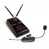
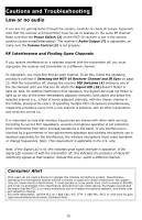
SYSTEM OPERATION MT-16A/R, MH-16, LK-16, or WH-16 Transmitter Note: The transmitter referred to below is one of the following: MT-16A/R, MH-16, LK-16 or WH-16, as provided with your system. Powering the Transmitter The transmitter each requires one AAA Battery (25, 29, 42, or 51). To install the battery, push the locking tabs on the Battery Cover (26, 28, 41, or 52) and push out to expose the Battery Compartment (23, 30, 45, or 50). Insert one fresh AAA battery according to the correct polarity as indicated on the transmitter body. Close the battery cover, ensuring the cover is snapped shut. A fresh AAA alkaline battery generally provides up to 6-8 hours of operation, but in order to ensure optimal performance it is recommended that the battery be replaced after six hours of use or as indicated by the Low Battery Indicator (21, 32, 47, or 49). The transmitters (MT-16A/R, MH-16 only) have a 15dB Pad (18) switch which can be selected to attenuate high output from instrument pick-up levels if needed to reduce distortion through the system. To attenuate, slide the switch in the direction of the arrow. Turning opposite the arrow indication is for standard 1:1 gain operation and is recommended for normal, optimal low-noise operation. The transmitters (MT-16A/R, MH-16 only) have an internal Audio Level Adjust (24, 34) to set the audio deviation level. It is accessed by inserting a small screwdriver into the slot. Turning this trim-pot counterclockwise reduces overall system audio output (thus lowering distortion but raising background noise), while turning clockwise increases overall system audio output (thus lowering background noise but raising distortion). The Audio Level Adjust is factory set to the mid position, which is the optimal setting for normal operation. As the batteries weaken, the Low Battery Indicator will flash to warn that the battery level is too low and should be replaced as soon as possible. To preserve battery life, turn the transmitter off when not in use. To turn the transmitter off, slide the Power Switch in the opposite direction of the arrow. To turn on the transmitter, slide the Power Switch (17, 35, 40, or 18) in the direction of the arrow. The Low Battery Indicator will flash once. The unit is now on and the receiver's RF Signal LED (10) will light up if the transmitter has been frequency synchronized to the receiver's selected frequency as per below. To turn it off, slide the power switch opposite direction, and the receiver RF Signal LED (10) should be off. Note: The Audio Level Adjust is not intended for high-input signal adjustment- the 15dB pad is provided for that purpose. It is for use only in extreme cases during which satisfactory audio cannot be achieved with the pad alone. Note: Set control carefully. If trim-pot is turned past minimum or maximum adjustment points, it may need to be backed up to achieve desired setting. 12
-
 1
1 -
2
-
3
-
4
-
5
-
6
-
 7
7 -
 8
8 -
 9
9 -
 10
10 -
 11
11 -
 12
12 -
 13
13 -
 14
14 -
 15
15 -
 16
16 -
 17
17 -
18
-
19
-
20
 |
 |
