Nady MHT-16 Manual - Page 7
Quick MHT-16 User Controls/Connections Guide
 |
View all Nady MHT-16 manuals
Add to My Manuals
Save this manual to your list of manuals |
Page 7 highlights
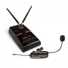
Quick MHT-16 User Controls/Connections Guide MH-16 Saxophone (Horn) Instrument Transmitter 28. BATTERY COMPARTMENT COVER To cover AAA battery, slide to open 29. BATTERY Single AAA alkaline or NiMH battery required for operation 30. BATTERY COMPARTMENT Insert one AAA battery, observing correct polarity 31. IR RECEPTOR SENSOR/WINDOW Infrared LED sensor for linking the TX to the RX during IR frequency download (See also ASCTM IR Sync Download section, page 6) 32. POWER & LOW BATTERY LED Flashes once at power up, continuous flashing indicates battery needs replacement 33. ANTENNA Permanently attached flexible antenna 34. INTERNAL AUDIO LEVEL ADJUST Remove battery to access slot and adjust internal trim-pot with small screwdriver for optimal input level setting. Note: This is to be done only in rare cases as factory level setting is already optimized for most horns and 15dB Pad also available. Note: Set control carefully. If trim-pot is turned past minimum and maximum adjustment points it may need to be backed up to achieve desired setting. 35. POWER SWITCH Slide in arrow direction to power transmitter On 36. 15dB ATTENUATION PAD Select to reduce the input gain by 15dB for higher level audio input signals 37. MOUNTING SCREW To secure the transmitter onto the bell of the horn 38. INPUT MIC For unidirectional pickup of horn's sound 7
-
 1
1 -
 2
2 -
 3
3 -
 4
4 -
 5
5 -
 6
6 -
 7
7 -
 8
8 -
 9
9 -
 10
10 -
 11
11 -
 12
12 -
13
-
14
-
15
-
16
-
17
-
18
-
19
-
20
 |
 |
