Nady MHT-16 Manual - Page 5
MGT-16 Receiver
 |
View all Nady MHT-16 manuals
Add to My Manuals
Save this manual to your list of manuals |
Page 5 highlights
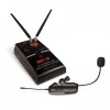
Quick User Controls/Connections Guide MGT-16 Receiver 1. ASC™ IR SYNC INFRARED LED WINDOW For downloading selected Channel (Frequency) to transmitter 2. POWER SWITCH Select OFF/MUTE/ON (MUTE=power On, audio output highly attenuated) 3. VOLUME CONTROL Adjusts the audio output level-at maximum setting the gain will be about +4dB over a direct instrument-to-cord-to-amp connection 4. CHANNEL SELECT DIP-SWITCH Select one of 16 pre-set channels per MGT-16 DIP-Switch Frequency Selection Chart (see page 20) 5. BATTERY COMPARTMENT Insert two AA batteries for optional DC operation, note correct polarity 6. BATTERY COMPARTMENT COVER Push tab to release hinged door 7. AUDIO OUTPUT JACK For connecting audio cable 8. DC INPUT JACK For connecting external AC/DC adapter for powering receiver 9. ANTENNAS Dual ¼ wave for best reception 10. SIGNAL LED (Green) Indicates the received signal from the transmitter 11. LOW BATTERY LED (Amber) Lights continuously to indicate batteries need replacement (if not using power adapter) 12. POWER ON LED (Red) will light indicating the receiver is operational 13. MUTE (SQUELCH) CONTROL Adjust with a small screwdriver inserted in slot. Controls the mute level for the receiver-turn counter-clockwise for maximum range; turn clockwise, if needed, to minimize noises from outside RF interference upon muting. Note: Set control carefully. If trim-pot is turned past minimum and maximum adjustment points it may need to be backed up to achieve desired setting. 14. ASC™ IR SYNC BUTTON Press to make the IR link download the receiver's selected frequency to the TX. First, turn on the system transmitter supplied (or turn off and then on again if already on) and position its IR window 6-12" away from the MGT-16's IR WINDOW (1), press the SYNC button once and wait one second for the transmitter to respond. If the IR data download is successful, the receiver SIGNAL LED (10) will light, indicating the transmitter is locked in and transmitting. 15. AA BATTERIES Two required for optional battery operation, alkaline or NiMH 16. POWER ADAPTER For AC operation (included) 5
-
 1
1 -
 2
2 -
 3
3 -
 4
4 -
 5
5 -
 6
6 -
 7
7 -
 8
8 -
 9
9 -
 10
10 -
 11
11 -
12
-
13
-
14
-
15
-
16
-
17
-
18
-
19
-
20
 |
 |
