Netgear CM500V Installation Guide - Page 8
Rear Panel, Table 1. LED descriptions Continued, Rear panel, Hardware Setup
 |
View all Netgear CM500V manuals
Add to My Manuals
Save this manual to your list of manuals |
Page 8 highlights
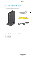
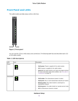
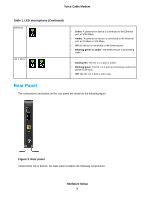
Voice Cable Modem Table 1. LED descriptions (Continued) Ethernet Tel 1 and 2 • Green. A powered-on device is connected to the Ethernet port at 1000 Mbps. • Amber. A powered-on device is connected to the Ethernet port at 10 Mbps or 100 Mbps. • Off. No device is connected to the Ethernet port. • Blinking green or amber. The Ethernet port is processing traffic. • Solid green. The Tel 1 or 2 port is online. • Blinking green. The Tel 1 or 2 port is processing a call or the phone is off-hook. • Off. The Tel 1 or 2 port is not in use. Rear Panel The connections and button on the rear panel are shown in the following figure. Figure 3. Rear panel Viewed from top to bottom, the back panel contains the following components: Hardware Setup 8
-
 1
1 -
2
-
 3
3 -
 4
4 -
 5
5 -
 6
6 -
 7
7 -
 8
8 -
 9
9 -
 10
10 -
 11
11 -
 12
12 -
 13
13 -
14
-
15
-
16
-
17
-
18
-
19
-
20
-
21
-
22
-
23
-
24
-
25
-
26
-
27
-
28
-
29
-
30
 |
 |

Table 1. LED descriptions (Continued)
•
Green
. A powered-on device is connected to the Ethernet
port at 1000 Mbps.
•
Amber
. A powered-on device is connected to the Ethernet
port at 10 Mbps or 100 Mbps.
•
Off
. No device is connected to the Ethernet port.
•
Blinking green or amber
. The Ethernet port is processing
traffic.
Ethernet
•
Solid green
.The Tel 1 or 2 port is online.
•
Blinking green
.The Tel 1 or 2 port is processing a call or the
phone is off-hook.
•
Off
.The Tel 1 or 2 port is not in use.
Tel 1 and 2
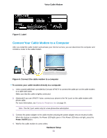
Rear Panel
The connections and button on the rear panel are shown in the following figure.
Figure 3. Rear panel
Viewed from top to bottom, the back panel contains the following components:
Hardware Setup
8
Voice Cable Modem