Netgear FVS124G FVS124G Reference Manual - Page 25
The Router’s Rear Panel - reset
 |
UPC - 606449040531
View all Netgear FVS124G manuals
Add to My Manuals
Save this manual to your list of manuals |
Page 25 highlights
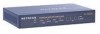
Reference Manual for the ProSafe VPN Firewall 25 with 4 Gigabit LAN and Dual WAN Ports Table 2-1. FVS124G front panel Object Activity PWR LED On (Green) Off TEST LED On (Amber) Blinking (Amber) Off WAN Port LEDs Link/Act LED On (Green) Blinking (Green) Off 100 LED On (Green) Off Active LED On (Green) On (Amber) Off Gigabit LAN Port LEDs Link/Act LED On (Green) Blinking (Green) Off Speed LED On (Green) On (Amber) Off Description Power is supplied to the firewall. Power is not supplied to the firewall. Test mode: The system is initializing or the initialization has failed. Writing to Flash memory (during upgrading or resetting to defaults). The system has booted successfully. The WAN port has detected a link with a connected Ethernet device. Data is being transmitted or received by the WAN port. The WAN port has no link. The WAN port is operating at 100 Mbps. The WAN port is operating at 10 Mbps. The WAN port has a valid Internet connection. The Internet connection is down or not being used. The WAN port is either not enabled or has no link. The LAN port has detected a link with a connected Ethernet device. Data is being transmitted or received by the LAN port. The LAN port has no link. The LAN port is operating at 1,000 Mbps. The LAN port is operating at 100 Mbps. The LAN port is operating at 10 Mbps. The Router's Rear Panel The rear panel of the FVS124G ProSafe VPN Firewall 25 with 4 Gigabit LAN and Dual WAN Ports (Figure 2-2) contains the factory defaults reset button, LAN and WAN ports, and DC power input connection. Introduction 2-7 202-10085-01, March 2005
-
 1
1 -
2
-
3
-
4
-
5
-
6
-
7
-
8
-
9
-
10
-
11
-
12
-
13
-
14
-
15
-
16
-
17
-
18
-
19
-
 20
20 -
 21
21 -
 22
22 -
 23
23 -
 24
24 -
 25
25 -
 26
26 -
 27
27 -
 28
28 -
 29
29 -
 30
30 -
31
-
32
-
33
-
34
-
35
-
36
-
37
-
38
-
39
-
40
-
41
-
42
-
43
-
44
-
45
-
46
-
47
-
48
-
49
-
50
-
51
-
52
-
53
-
54
-
55
-
56
-
57
-
58
-
59
-
60
-
61
-
62
-
63
-
64
-
65
-
66
-
67
-
68
-
69
-
70
-
71
-
72
-
73
-
74
-
75
-
76
-
77
-
78
-
79
-
80
-
81
-
82
-
83
-
84
-
85
-
86
-
87
-
88
-
89
-
90
-
91
-
92
-
93
-
94
-
95
-
96
-
97
-
98
-
99
-
100
-
101
-
102
-
103
-
104
-
105
-
106
-
107
-
108
-
109
-
110
-
111
-
112
-
113
-
114
-
115
-
116
-
117
-
118
-
119
-
120
-
121
-
122
-
123
-
124
-
125
-
126
-
127
-
128
-
129
-
130
-
131
-
132
-
133
-
134
-
135
-
136
-
137
-
138
-
139
-
140
-
141
-
142
-
143
-
144
-
145
-
146
-
147
-
148
-
149
-
150
-
151
-
152
-
153
-
154
-
155
-
156
-
157
-
158
-
159
-
160
-
161
-
162
-
163
-
164
-
165
-
166
-
167
-
168
-
169
-
170
-
171
-
172
-
173
-
174
-
175
-
176
-
177
-
178
-
179
-
180
-
181
-
182
-
183
-
184
-
185
-
186
-
187
-
188
-
189
-
190
-
191
-
192
-
193
-
194
-
195
-
196
-
197
-
198
-
199
-
200
-
201
-
202
-
203
-
204
-
205
-
206
-
207
-
208
-
209
-
210
-
211
-
212
-
213
-
214
-
215
-
216
-
217
-
218
-
219
-
220
-
221
-
222
-
223
-
224
-
225
-
226
-
227
-
228
-
229
-
230
-
231
-
232
-
233
-
234
-
235
-
236
-
237
-
238
 |
 |
