Netgear GS110TP-100NAS GS110TP Hardware Installation Guide - Page 13
System LEDs, Device Hardware Interfaces, RJ-45 Ports
 |
View all Netgear GS110TP-100NAS manuals
Add to My Manuals
Save this manual to your list of manuals |
Page 13 highlights
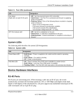
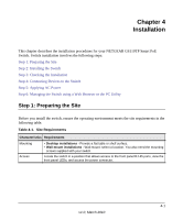
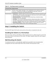
GS110TP Hardware Installation Guide Table 2-1. Port LEDs (continued) LED PoE Status (Right LED on each RJ-45 port) SFP Port Indicate LED Designation • Off = No PoE powered device (PD) connected. • Solid Green = The PoE PD is connected and the port is supplying power successfully. • Flashing Yellow = One of the following failures resulted in stopping power to that port: - Short circuit on PoE power circuit. - PoE power demand exceeds power available. - PoE current exceeds PD's classification. - Out of proper voltage band (44 ~ 57 VDC). • Off = No link is established on the port. • Solid Green = A valid link is established on the port. • Flashing Green = Packet transmission or reception is occurring on the port. System LEDs The following table describes the system LED designations. Table 2-2. System LEDs LED Power/Status LED PoE MAX LED Designation • Solid Green = Power is supplied to the switch and the switch is operating normally. • Solid Yellow = The switch is booting. • Off = Power is disconnected. • Off = There is at least 7W of PoE power available for another device. • Solid Yellow = Less than 7W of PoE power is available. • Flashing Yellow = The PoE MAX LED was active in the previous two minutes. Device Hardware Interfaces RJ-45 Ports RJ-45 ports are autosensing ports. When inserting a cable into an RJ-45 port, the switch automatically ascertains the maximum speed (10, 100, or 1000 Mbps) and duplex mode (halfduplex or full-duplex) of the attached device. All ports support only unshielded twisted-pair (UTP) cable terminated with an 8-pin RJ-45 plug. Physical Description 2-3 v1.0, March 2010
-
 1
1 -
2
-
3
-
4
-
5
-
6
-
7
-
 8
8 -
 9
9 -
 10
10 -
 11
11 -
 12
12 -
 13
13 -
 14
14 -
 15
15 -
 16
16 -
 17
17 -
 18
18 -
19
-
20
-
21
-
22
-
23
-
24
-
25
-
26
-
27
-
28
-
29
-
30
-
31
-
32
 |
 |
