Netgear GS110TP-100NAS GS110TP Hardware Installation Guide - Page 20
Step 5: Applying AC Power, Step 6: Managing the Switch using a Web Browser or the PC Utility
 |
View all Netgear GS110TP-100NAS manuals
Add to My Manuals
Save this manual to your list of manuals |
Page 20 highlights
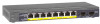
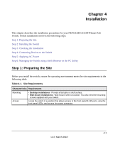
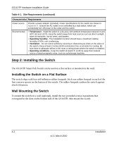
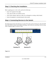
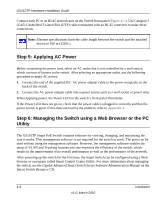
GS110TP Hardware Installation Guide Connect each PC to an RJ-45 network port on the Switch front panel (Figure 4-1 ). Use Category 5 (Cat5) Unshielded Twisted-Pair (UTP) cable terminated with an RJ-45 connector to make these connections. Note: Ethernet specifications limit the cable length between the switch and the attached device to 100 m (328 ft.). Step 5: Applying AC Power Before connecting the power cord, select an AC outlet that is not controlled by a wall switch, which can turn off power to the switch. After selecting an appropriate outlet, use the following procedure to apply AC power: 1. Connect the end of the supplied IEC AC power adapter cable to the power receptacle on the back of the switch. 2. Connect the AC power adapter cable into a power source such as a wall socket or power strip. When applying power, the Power LED on the switch's front panel illuminates. If the Power LED does not go on, check that the power cable is plugged in correctly and that the power source is good. If this does not resolve the problem, refer to Appendix A . Step 6: Managing the Switch using a Web Browser or the PC Utility The GS110TP Smart PoE Switch contains software for viewing, changing, and monitoring the way it works. This management software is not required for the switch to work. The ports can be used without using the management software. However, the management software enables the setup of VLAN and Trunking features and also improves the efficiency of the switch, which results in the improvement of its overall performance as well as the performance of the network. After powering up the switch for the first time, the Smart Switch can be configured using a Web browser or a program called Smart Control Center Utility. For more information about managing the switch, see the Gigabit Advanced Smart Switch Series Software Administration Manual on the Smart Switch Resource CD. 4-4 Installation v1.0, March 2010
-
 1
1 -
2
-
3
-
4
-
5
-
6
-
7
-
8
-
9
-
10
-
11
-
12
-
13
-
14
-
 15
15 -
 16
16 -
 17
17 -
 18
18 -
 19
19 -
 20
20 -
 21
21 -
 22
22 -
 23
23 -
 24
24 -
 25
25 -
26
-
27
-
28
-
29
-
30
-
31
-
32
 |
 |