Netgear GS510TPP Hardware Installation Guide
Netgear GS510TPP Manual
 |
View all Netgear GS510TPP manuals
Add to My Manuals
Save this manual to your list of manuals |
Netgear GS510TPP manual content summary:
- Netgear GS510TPP | Hardware Installation Guide - Page 1
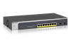
ProSAFE 8-Port Gigabit Smart Managed Switch with PoE+ and 2 SFP Ports Hardware Installation Guide Models GS510TLP and GS510TPP February 2017 202-11734-01 350 E. Plumeria Drive San Jose, CA 95134 USA - Netgear GS510TPP | Hardware Installation Guide - Page 2
ProSAFE 8-Port Gigabit Smart Managed Switch with PoE+ and 2 SFP Ports Support Thank you for purchasing this NETGEAR product. You can visit www.netgear.com/support to register your product, get help, access the latest downloads and user manuals, and join our community. We recommend that you use only - Netgear GS510TPP | Hardware Installation Guide - Page 3
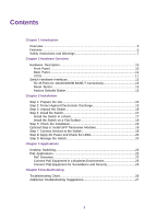
Overview...5 Features...5 Safety Instructions and Warnings 7 Chapter 2 Hardware Overview Hardware Description 10 Front Panel...10 Back Panel...11 LEDs...11 Switch Hardware Interfaces 12 RJ-45 Ports for 10/100/1000M BASE-T Connectivity 13 Reset Button 13 Factory Defaults Button 13 Chapter - Netgear GS510TPP | Hardware Installation Guide - Page 4
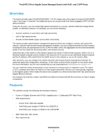
serves as an introduction to the switch and includes the following sections: • Overview • Features • Safety Instructions and Warnings Note For more information about the topics that are covered in this manual, visit the support website at support.netgear.com. Note For technical specifications, see - Netgear GS510TPP | Hardware Installation Guide - Page 5
program for very basic setup. For more information, see the user manual that you can download from downloadcenter.netgear.com. You can install the switch freestanding or rack mounted in a wiring closet or equipment room. The switch is IEEE compliant and offers low latency for high-speed networking - Netgear GS510TPP | Hardware Installation Guide - Page 6
GS510TPP (fan) • Acoustic noise: 32 dBA (GS510TTP). • 20 Gbps switch fabric full duplex non-blocking. • 500 Desktop Case. • AutoSensing and autonegotiating capabilities for all ports. • Auto UplinkTM technology is supported Support for Power over Ethernet (PoE+). • NETGEAR 1p Class of Service (QoS) - - Netgear GS510TPP | Hardware Installation Guide - Page 7
ProSAFE 8-Port Gigabit Smart Managed Switch with PoE+ and 2 SFP Ports Safety Instructions NETGEAR product which may not be covered by NETGEAR's warranty. • Observe and follow service markings: - Do not service section in your troubleshooting guide, or contact your trained service provider. • Do - Netgear GS510TPP | Hardware Installation Guide - Page 8
ProSAFE 8-Port Gigabit Smart Managed Switch with PoE+ and 2 SFP Ports - 115V, 60 Hz in most of North and South America and some Far Eastern countries such as South Korea and - Netgear GS510TPP | Hardware Installation Guide - Page 9
Hardware Overview This chapter describes the switch hardware features. The chapter includes the following sections: • Hardware Description • Switch Hardware Interfaces 2 9 - Netgear GS510TPP | Hardware Installation Guide - Page 10
switch provides eight 10/100/1000M BASE-T RJ-45 PoE ports and 2 dedicated SFP ports.The following figures show the front panel. Figure 1. GS510TLP front view Number 1 2 3 4 5 6 7 Description Power PoE Max LED (see LEDs on page 11). Reset Recessed Factory Defaults 2. GS510TPP front view Number 1 - Netgear GS510TPP | Hardware Installation Guide - Page 11
ProSAFE 8-Port Gigabit Smart Managed Switch with PoE+ and 2 SFP Ports Number 5 6 7 8 Description Recessed Factory Defaults button RJ-45 Number 1 2 Description Kensington lock slot AC power connector Figure 4. GS510TPP back panel Number 1 2 Description Kensington lock slot AC power connector - Netgear GS510TPP | Hardware Installation Guide - Page 12
ProSAFE 8-Port Gigabit Smart Managed Switch with PoE+ and 2 SFP Ports Table 1. LEDs on switch LED Power LED Description • Solid green . The device is powered on. • Solid amber. The device is booting. • Off. Power is not supplied to the device. Fan LED (GS510TPP only) • Solid amber. The fans - Netgear GS510TPP | Hardware Installation Guide - Page 13
2. Press the recessed Reset button for about three seconds. The switch reboots. Factory Defaults Button The switch provides a Factory Defaults button on the front panel so that you can return the switch to its factory settings. To return the switch to its factory default settings: 1. Insert a device - Netgear GS510TPP | Hardware Installation Guide - Page 14
the steps described in the following sections: • Step 1: Prepare the site • Step 2: Protect Against Electrostatic Discharge • Step 3: Unpack the Switch • Step 4: Install the Switch • Step 5: Check the Installation • Optional Step 6: Install SFP Transceiver Modules • Step 7: Connect Devices to the - Netgear GS510TPP | Hardware Installation Guide - Page 15
ProSAFE 8-Port Gigabit Smart Managed Switch with PoE+ and 2 SFP Ports Step 1: Prepare the site Before you install the switch, ensure that the operating environment meets the site requirements that are listed in the following table. Table 2. Site Requirements Characteristics Mounting Access Power - Netgear GS510TPP | Hardware Installation Guide - Page 16
ProSAFE 8-Port Gigabit Smart Managed Switch with PoE+ and 2 SFP Ports • When unpacking a static strap. Step 3: Unpack the Switch The following figure shows the package contents for the GS510TLP.The package contents for the GS510TPP are the same. Figure 5. Switch package contents Check the contents of - Netgear GS510TPP | Hardware Installation Guide - Page 17
ProSAFE 8-Port Gigabit Smart Managed Switch with PoE+ and 2 SFP Ports c. Rubber caps for the SFP sockets d. Rack-mounting kit e. Rubber footpads for tabletop installation f. Quick installation guide g. Resource CD with NETGEAR Smart Control Center utility 5. If any item is missing or damaged, - Netgear GS510TPP | Hardware Installation Guide - Page 18
ProSAFE 8-Port Gigabit Smart Managed Switch with PoE+ and 2 SFP Ports Note Rack installation for the both GS510TLP and GS510TPP is the same. Install the Switch on a Flat Surface The switch ships with four self-adhesive rubber footpads. To install the switch on a flat surface: 1. Stick one rubber - Netgear GS510TPP | Hardware Installation Guide - Page 19
ProSAFE 8-Port Gigabit Smart Managed Switch with module into one of the SFP ports of the switch. Note Contact your NETGEAR sales office to purchase these modules. If you do the Switch The following procedure describes how to connect computers to the switch's RJ-45 ports.The switch supports Auto - Netgear GS510TPP | Hardware Installation Guide - Page 20
basic setup. For more information about managing the switch, see the installation guide on the resource CD and the user manual that you can download from downloadcenter.netgear.com. Note The switch's default IP address is 192.168.0.239 and its default subnet mask is 255.255.255.0. Installation 20 - Netgear GS510TPP | Hardware Installation Guide - Page 21
4 The switch is designed to provide flexibility in configuring network connections. The switch can be used as your only network traffic-distribution device or with 10 Mbps, 100 Mbps, and 1 Gbps hubs, routers, and switches. This chapter includes the following sections: • Desktop Switching • PoE - Netgear GS510TPP | Hardware Installation Guide - Page 22
ProSAFE 8-Port Gigabit Smart Managed Switch with PoE+ and 2 SFP Ports Desktop Switching You can use the switch as a desktop switch to build a small network that provides up to 1 Gbps access to a file server. With 1G connections, the switch always functions in full-duplex mode. Any switch port that - Netgear GS510TPP | Hardware Installation Guide - Page 23
for the attached devices exceed the total power budget of the switch, the power to the device on the highest-numbered PoE port is disabled to make sure that the devices connected to the higher-priority, lower-numbered PoE ports are supported first. It is important to note that although a device is - Netgear GS510TPP | Hardware Installation Guide - Page 24
ProSAFE 8-Port Gigabit Smart Managed Switch with PoE+ and 2 SFP Ports Figure 8. Sample switch surveilliance and security application Line color Green Black Description PoE (such as security cameras) Non-PoE (such as ReadyNAS or Internet) Applications 24 - Netgear GS510TPP | Hardware Installation Guide - Page 25
Troubleshooting 5 This chapter provides information about troubleshooting the switch. The chapter includes the following sections: • Troubleshooting Chart • Additional Troubleshooting Suggestions 25 - Netgear GS510TPP | Hardware Installation Guide - Page 26
ProSAFE 8-Port Gigabit Smart Managed Switch with PoE+ and 2 SFP Ports Troubleshooting Chart The following table lists symptoms, causes, and solutions for possible problems. Table 3. Troubleshooting Chart Sympton Power LED is off. Cause No power is received. Solution • Check the power cable - Netgear GS510TPP | Hardware Installation Guide - Page 27
the integrity of the switch by resetting it. To reset the switch, disconnect the AC power from the switch and then reconnect the AC power. If the problem continues, contact NETGEAR technical support. For more information, visit the support website at support.netgear.com. • Autonegotiation. The RJ
-
 1
1 -
 2
2 -
 3
3 -
 4
4 -
 5
5 -
 6
6 -
 7
7 -
8
-
9
-
10
-
11
-
12
-
13
-
14
-
15
-
16
-
17
-
18
-
19
-
20
-
21
-
22
-
23
-
24
-
25
-
26
-
27
 |
 |

ProSAFE 8-Port
Gigabit Smart
Managed Switch
with PoE+
and 2
SFP Ports
Hardware Installation
Guide
Models GS510TLP and GS510TPP
February 2017
202-11734-01
350 E. Plumeria Drive
San Jose, CA 95134
USA