Netgear GS510TPP Hardware Installation Guide - Page 12
Switch Hardware Interfaces, Table 1. LEDs on switch, Hardware Overview
 |
View all Netgear GS510TPP manuals
Add to My Manuals
Save this manual to your list of manuals |
Page 12 highlights
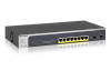
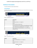
ProSAFE 8-Port Gigabit Smart Managed Switch with PoE+ and 2 SFP Ports Table 1. LEDs on switch LED Power LED Description • Solid green . The device is powered on. • Solid amber. The device is booting. • Off. Power is not supplied to the device. Fan LED (GS510TPP only) • Solid amber. The fans has failed. • Off. The fan is operating normally. RJ-45 SPD Mode LED Upper LED Row (RJ-45 SPD state) (Link, Speed, Activity) for copper ports 1 to 8 • Off: No link is established. • Solid green: A valid 1000 Mbps link is established. • Blinking green. The port is transmitting or receiving packets at 1000 Mbps. • Solid amber. A valid 10/100 Mbps link is established. • Blinking amber. The port is transmitting or receiving packets at 10/100 Mbps. Lower LED Row (PoE state) • Off: PoE mode is off. • Solid green: PoE mode is on. • Solid amber: A PoE fault occurred. Link/ACT Mode LED for SFP fiber ports • • • Off: No SFP module link is established. Solid green. A valid 1000Mbps link is established. Blinking green. The SFP fiber port is transmitting or receiving packets at 1000 Mbps. PoE Max LED • Off. More than 7W of PoE power is available. • Solid amber. Less than 7W of PoE power is available. • Blinking amber. At least once during the previous two minutes, less than 7W of PoE power was available. Switch Hardware Interfaces The following sections describe the hardware interfaces on the switch. Hardware Overview 12
-
 1
1 -
2
-
3
-
4
-
5
-
6
-
 7
7 -
 8
8 -
 9
9 -
 10
10 -
 11
11 -
 12
12 -
 13
13 -
 14
14 -
 15
15 -
 16
16 -
 17
17 -
18
-
19
-
20
-
21
-
22
-
23
-
24
-
25
-
26
-
27
 |
 |
