Netgear GS716Tv2 GS716Tv2/GS724Tv3 Hardware manual - Page 12
GS724T Front and Back Panel Configuration - reset
 |
View all Netgear GS716Tv2 manuals
Add to My Manuals
Save this manual to your list of manuals |
Page 12 highlights
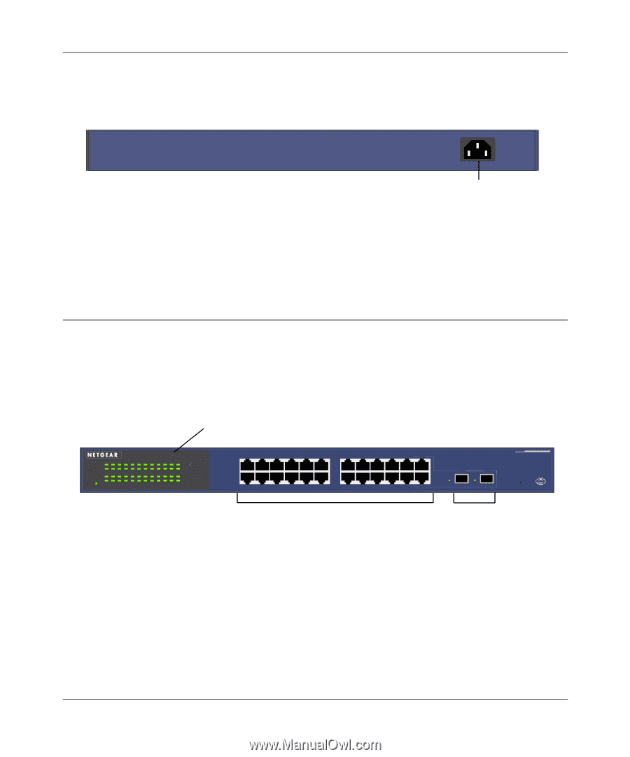
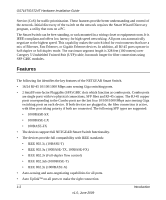
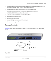
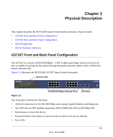
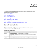
GS716T/GS724T Hardware Installation Guide • System LEDs Figure 2-2 illustrates the NETGEAR GS716T Smart Switch back panel: 100-240V ~ 50-60Hz Figure 2-2 RS-232 Power Connector The back panel contains the following: • A 100-240VAC/50-60 Hz universal input, which is a standard AC power receptacle for accommodating the supplied power cord. GS724T Front and Back Panel Configuration The GS724T is a 24-port 10/100/1000 Mbps Smart Switch + 2 SFP Combo ports switch. Every RJ-45 port is capable of sensing the line speed and negotiating the operation duplex mode with the link partner automatically Figure 2-3 illustrates the NETGEAR GS724T Smart Switch front panel: System LEDs Reset PWR ® ProSafe 24 Port Gigabit Smart Switch 1 3 5 7 9 11 13 15 17 19 21 23 LINK/ACT SPD Green (1000M) Yellow (100M) FDX 2 4 6 8 10 12 14 16 18 20 22 24 LINK/ACT SPD FDX 1 3 5 7 9 11 2 4 6 8 10 12 13 15 17 19 21 23T 14 16 18 20 22 24T 23F 24F Link/ Link/ ACT ACT MODEL GS724T Auto™ Uplink Factory Defaults Figure 2-3 10/100/1000 Mbps Ethernet Ports SFP Ports The front panel contains the following: • 24 RJ-45 connectors for 10/100/1000 Mbps auto-sensing Gigabit Ethernet switching ports. • Two slots for SFP slots for SFP modules supporting 1000 (1000BASE-SX/LX)/100 Mbps SFP. • Reset button to restart the device. • Recessed default reset button to restore the device back to the factory defaults. 2-6 Physical Description v1.0, June 2009
-
 1
1 -
2
-
3
-
4
-
5
-
6
-
 7
7 -
 8
8 -
 9
9 -
 10
10 -
 11
11 -
 12
12 -
 13
13 -
 14
14 -
 15
15 -
 16
16 -
 17
17 -
18
-
19
-
20
-
21
-
22
-
23
-
24
-
25
-
26
-
27
-
28
-
29
-
30
-
31
 |
 |