Netgear GS716Tv2 GS716Tv2/GS724Tv3 Hardware manual - Page 21
Step 6: Applying AC Power, Appendix
 |
View all Netgear GS716Tv2 manuals
Add to My Manuals
Save this manual to your list of manuals |
Page 21 highlights
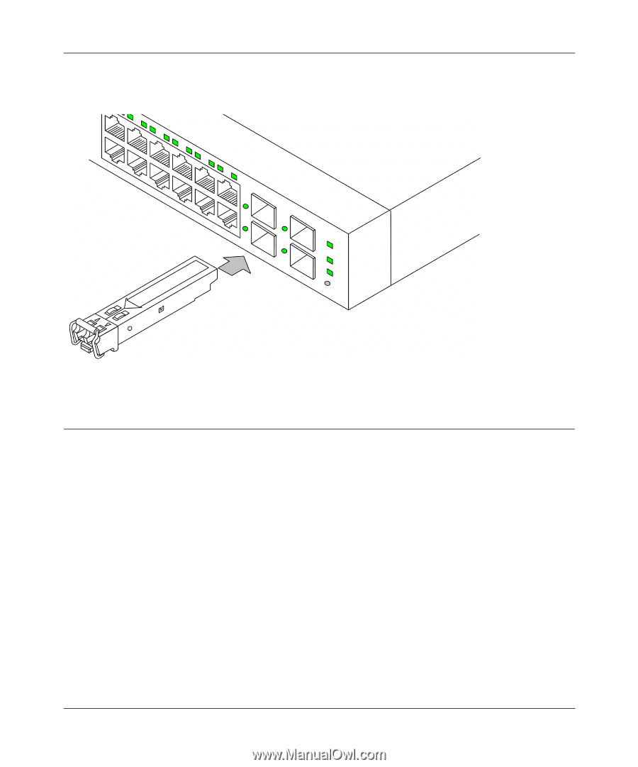
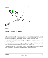
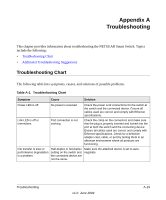
GS716T/GS724T Hardware Installation Guide Insert the SFP module into the SFP module bay. Press firmly to ensure the module seats into the connector. Figure 4-3 Step 6: Applying AC Power NETGEAR Smart Switch does not have an ON/OFF switch. The method of applying or removing AC power is by connecting or disconnecting the power cord. Before connecting the power cord, select an AC outlet that is not controlled by a wall switch, which can turn off power to the switch. After selecting an appropriate outlet, use the following procedure to apply AC power. 1. Connect the female end of the supplied AC power adapter cable to the power receptacle on the back of the switch. 2. Connect the 3-pronged end of the AC power adapter cable to a grounded 3-pronged AC outlet. When applying power, the Power LED on the switch's front panel is Green. If the Power LED does not go on, check that the power cable is plugged in correctly and that the power source is good. If this does not resolve the problem, refer to Appendix A . Installation v1.0, June 2009 4-17
-
 1
1 -
2
-
3
-
4
-
5
-
6
-
7
-
8
-
9
-
10
-
11
-
12
-
13
-
14
-
15
-
 16
16 -
 17
17 -
 18
18 -
 19
19 -
 20
20 -
 21
21 -
 22
22 -
 23
23 -
 24
24 -
 25
25 -
 26
26 -
27
-
28
-
29
-
30
-
31
 |
 |