Netgear GS716Tv2 GS716Tv2/GS724Tv3 Hardware manual - Page 18
Step 2: Installing the Switch, Installing the Switch on a Flat Surface
 |
View all Netgear GS716Tv2 manuals
Add to My Manuals
Save this manual to your list of manuals |
Page 18 highlights
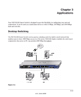
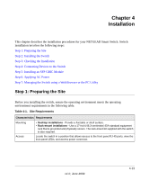
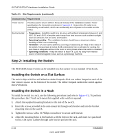
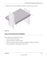
GS716T/GS724T Hardware Installation Guide Table 4-1. Site Requirements (continued) Characteristics Requirements Power source Environmental Provide a power source within 6 feet (1.8 meters) of the installation location. Power specifications for the switch are shown in Appendix A . Ensure the AC outlet is not controlled by a wall switch, which can accidentally turn off power to the outlet and the switch. • Temperature - Install the switch in a dry area, with ambient temperature between 0 and 55ºC (32 and 131ºF). Keep the switch away from heat sources such as direct sunlight, warm air exhausts, hot-air vents, and heaters. • Operating humidity - The installation location should have a maximum relative humidity of 90%, non-condensing. • Ventilation - Do not restrict airflow by covering or obstructing air inlets on the sides of the switch. Keep at least 2 inches (5.08 centimeters) free on all sides for cooling. Be sure there is adequate airflow in the room or wiring closet where the switch is installed. • Operating conditions - Keep the switch at least 6 ft. (1.83 m) away from nearest source of electromagnetic noise, such as a photocopy machine. Step 2: Installing the Switch The NETGEAR Smart Switch can be installed on a flat surface or in a standard 19-inch rack. Installing the Switch on a Flat Surface The switch ships with four self-adhesive rubber footpads. Stick one rubber footpad on each of the four concave spaces on the bottom of the switch. The rubber footpads cushion the switch against shock/vibrations. Installing the Switch in a Rack To install the switch in a rack, use the following procedure (and refer to Figure 4-1). To perform this procedure, the 17-inch rack-mount kit supplied with switch is required. 1. Attach the supplied mounting brackets to the side of the switch. 2. Insert the screws provided in the rack-mount kit through each bracket and into the bracket mounting holes in the switch. 3. Tighten the screws with a #1 Phillips screwdriver to secure each bracket. 4. Align the mounting holes in the brackets with the holes in the rack, and insert two pan-head screws with nylon washers through each bracket and into the rack. 4-14 v1.0, June 2009 Installation
-
 1
1 -
2
-
3
-
4
-
5
-
6
-
7
-
8
-
9
-
10
-
11
-
12
-
 13
13 -
 14
14 -
 15
15 -
 16
16 -
 17
17 -
 18
18 -
 19
19 -
 20
20 -
 21
21 -
 22
22 -
 23
23 -
24
-
25
-
26
-
27
-
28
-
29
-
30
-
31
 |
 |
