Netgear GS724AT GS724AT Hardware manual
Netgear GS724AT - ProSafe Gigabit Smart Switch Manual
 |
UPC - 606449056907
View all Netgear GS724AT manuals
Add to My Manuals
Save this manual to your list of manuals |
Netgear GS724AT manual content summary:
- Netgear GS724AT | GS724AT Hardware manual - Page 1
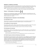
GS700AT Hardware Installation Guide NETGEAR, Inc. 4500 Great America Parkway Santa Clara, CA 95054 USA 202-10359-01 January 2008 - Netgear GS724AT | GS724AT Hardware manual - Page 2
upgrades. NETGEAR, INC. Support Information Phone: 1-888-NETGEAR, for US & Canada only. For other countries, see your Support information card. E-mail: [email protected] North American NETGEAR website: http://www.netgear.com Trademarks NETGEAR, the NETGEAR logo, ProSafe instructions das Switch gemäß - Netgear GS724AT | GS724AT Hardware manual - Page 3
firmware limits operation to only the channels allowed in a particular Region or Country. Therefore, all options described in this user's guide NETGEAR, Inc., 4500 Great America Parkway, Santa Clara, CA 95054, declare under our sole responsibility that the model GS700AT Smart Switch Instructions This - Netgear GS724AT | GS724AT Hardware manual - Page 4
expressly approved by NETGEAR, Inc., could void the user's right to operate the equipment. D Canadian Department of Communications Radio Interference Regulations This digital apparatus (GS700AT Smart Switch with Gigabit Ports) does not exceed the Class B limits for radio-noise emissions from digital - Netgear GS724AT | GS724AT Hardware manual - Page 5
AC Power 2-33 Step 7: Managing the Switch through a Web Browser or the PC Utility for Initial Configuration ...2-34 Chapter 3 Physical Description GS724 AT Front and Back Panel Configuration 3-19 LED Designations ...3-20 System LEDs ...3-20 Device Hardware Interfaces 3-20 RJ-45 Ports ...3-21 v v1 - Netgear GS724AT | GS724AT Hardware manual - Page 6
Installation Guide SFP GBIC Module 3-21 Factory Defaults Button 3-21 Appendix A Troubleshooting Troubleshooting Chart A-1 Additional Troubleshooting Suggestions A-2 Network Adapter Cards A-2 Configuration ...A-2 Switch Integrity ...A-2 Auto-negotiation ...A-3 Appendix B Technical Specifications - Netgear GS724AT | GS724AT Hardware manual - Page 7
NETGEAR Smart Switch. The NETGEAR®GS700AT Hardware Installation Guide describes how to install, configure and troubleshoot the smart switch. The information in this manual User input, IP addresses, GUI screen text Command prompt, CLI text, code URL links • Formats. This manual uses the following - Netgear GS724AT | GS724AT Hardware manual - Page 8
according to these specifications: Product Version Manual Publication Date GS700AT Smart Switch December 2007 Note: Product updates are available on the NETGEAR, Inc. web site at http://kbserver.netgear.com/main.asp. How to Use This Manual The HTML version of this manual includes the following - Netgear GS724AT | GS724AT Hardware manual - Page 9
top left of any page. - Click the Complete PDF Manual link at the top left of any page in the manual. The PDF version of the complete manual opens in a browser window. - Click the print icon in the upper left of the window. Tip: If your printer supports printing two pages on a single sheet of paper - Netgear GS724AT | GS724AT Hardware manual - Page 10
GS700AT Hardware Installation Guide xii v1.0, December 2007 - Netgear GS724AT | GS724AT Hardware manual - Page 11
, and control of the network. With a Web-based Graphical User Interface (GUI), you can view the switch's many features and use them in a simple and intuitive manner. The switch's management features include configuration for port and switch information, VLAN for traffic control, port trunking for - Netgear GS724AT | GS724AT Hardware manual - Page 12
Guide The GS700AT Smart Switch can be free-standing, or rack mounted in a wiring closet or equipment room. It is IEEE-compliant and offers low latency for high-speed networking. All ports can automatically negotiate to the highest speed. This capability makes the switch The NETGEAR Smart Switch can - Netgear GS724AT | GS724AT Hardware manual - Page 13
switching ports on each device. The following SFP types are supported: • 1000Base-SX • 1000Base-LX • The device support full Netgear Smart Switch all ports to make the right connection. • Automatic address-learning function to build the packet-forwarding information table. The table contains up - Netgear GS724AT | GS724AT Hardware manual - Page 14
packet loss/frame drops. • Half-duplex back-pressure control. • Per port LEDs, System LEDs. • Internal power supply. • Standard 1U high, rack mountable 19"chassis. • Fan speed control supported (optional). Package Contents Figure 1-2 shows the package contents of the NETGEAR Smart Switch. Figure - Netgear GS724AT | GS724AT Hardware manual - Page 15
GS700AT Hardware Installation Guide • Warranty/Support Information Card If any item is missing or damaged, contact the place of purchase immediately. Introduction v1.0, January 2008 1-17 - Netgear GS724AT | GS724AT Hardware manual - Page 16
GS700AT Hardware Installation Guide 1-18 v1.0, January 2008 Introduction - Netgear GS724AT | GS724AT Hardware manual - Page 17
Installing an SFP GBIC Module" "Step 6: Applying AC Power" "Step 7: Managing the Switch through a Web Browser or the PC Utility for Initial Configuration" Step 1: Preparing the Site Before installing the switch, ensure the operating environment meets the requirements in the following table. Table - Netgear GS724AT | GS724AT Hardware manual - Page 18
Hardware Installation Guide Table 2-1. Site Requirements (continued) Characteristics Requirements Power source Environmental Provide a power source within 6 feet (1.8 meters) of the installation location. Power specifications for the switch are shown in Appendix A , "Troubleshooting". Ensure the - Netgear GS724AT | GS724AT Hardware manual - Page 19
GS700AT Hardware Installation Guide 5. Tighten the screws with a #2 Phillips screwdriver to secure the switch in the rack. Figure 2-1 Note: Always install devices from the bottom of the to the top. This will prevent the rack from over balancing and - Netgear GS724AT | GS724AT Hardware manual - Page 20
Guide Step 4: Connecting Devices to the Switch The following procedure describes how to connect PCs to the switch's RJ-45 ports. The NETGEAR Smart Switch -45 connector for these connections. Note: Ethernet specifications limit the cable length between the switch and the attached device to 100 m (328 - Netgear GS724AT | GS724AT Hardware manual - Page 21
GS700AT Hardware Installation Guide 1. Insert the SFP module into the SFP module bay. 2. Press firmly to ensure the module seats into the connector. Figure 2-3 Step 6: Applying AC Power NETGEAR Smart Switch does not have an ON/OFF switch. The method of applying or removing AC power is by - Netgear GS724AT | GS724AT Hardware manual - Page 22
using a Web browser or a utility program called SmartWizard Discovery. For more information about managing the switch, see the Software Manual on the Smart Switch Resource CD. Note: When the device powers up, there is a default IP address already configured on the device. The default IP address is - Netgear GS724AT | GS724AT Hardware manual - Page 23
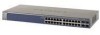
Interfaces" GS724 AT Front and Back Panel Configuration The GS724AT is a 24-Ports 10/100/1000M + 4 SFP Combo ports Smart switch. Every RJ45 port is capable of sensing the line speed and negotiating the operation duplex mode with the link partner automatically. Figure 3-1 illustrates the NETGEAR - Netgear GS724AT | GS724AT Hardware manual - Page 24
Hardware Installation Guide Figure 3-2 illustrates the NETGEAR GS724AT Smart Switch back panel: switch and is operating normally. • Off - FAN is operating normally. • Solid Yellow - FAN has failed. Device Hardware Interfaces This section provides information for the following hardware interfaces - Netgear GS724AT | GS724AT Hardware manual - Page 25
SFP GBIC module. Factory Defaults Button The Smart Switch has a Factory default button to enable clearing the current configuration and returning the device back to the factory settings. This removes all settings, including the password, VLAN settings and port configurations. Physical Description - Netgear GS724AT | GS724AT Hardware manual - Page 26
GS700AT Hardware Installation Guide 3-22 v1.0, December 2007 Physical Description - Netgear GS724AT | GS724AT Hardware manual - Page 27
problems. Table A-1. Troubleshooting Chart Symptom Cause Solution Power LED is off. No power is received. Check the power cord connections for the switch at the switch and the connected device. Ensure all cables are used correctly and comply with the Ethernet specifications. Link LED - Netgear GS724AT | GS724AT Hardware manual - Page 28
If required, verify the integrity of the switch by resetting the switch. To reset the switch, disconnect the AC power from the switch and then reconnect AC source. If the problem continues, contact NETGEAR technical support. In North America, call 1-888-NETGEAR. If you are outside of North America - Netgear GS724AT | GS724AT Hardware manual - Page 29
Installation Guide Auto-negotiation The RJ-45 ports negotiate the correct duplex mode and speed if the device at the other end of the link supports auto-negotiation. If the device does not support auto negotiation, the switch only determines the speed correctly and the duplex mode defaults to - Netgear GS724AT | GS724AT Hardware manual - Page 30
GS700AT Hardware Installation Guide A-4 Troubleshooting v1.0, December 2007 - Netgear GS724AT | GS724AT Hardware manual - Page 31
Class of Service (CoS) Interface 24-RJ-45 connectors for 10Base-T,100Base-TX and 1000Base-(Auto Uplink™ on all ports). Four Small Form-factor Pluggable (SFP) slots , supported 1000(1000Base-SX/LX)/100M SFP LEDs Per port LEDs, System LEDs, Power LED and Fan LED. Performance Specifications Forwarding - Netgear GS724AT | GS724AT Hardware manual - Page 32
GS700AT Hardware Installation Guide 100-240VAC/50-60 Hz universal input Physical Specifications Dimensions (H x W x D): GS724AT: 1.6 x 17.3 x 8.1 / 43 x 440 x 205 (in/mm) Weight: 6.835 / 3.1 (lbs/kg) Environmental Specifications Operating temperature: 0 to 55°C (32 to 131°F) Storage temperature: -20 - Netgear GS724AT | GS724AT Hardware manual - Page 33
GS700AT Hardware Installation Guide Modules AGM731F 1000Base-SX SFP GBIC for multimode fiber AGM732F 1000Base-LX SFP GBIC for single mode fiber AGM733 1000Base-LZ GBIC for long haul single mode fiber Technical Specifications B-3 v1.0, December 2007 - Netgear GS724AT | GS724AT Hardware manual - Page 34
GS700AT Hardware Installation Guide B-4 Technical Specifications v1.0, December 2007 - Netgear GS724AT | GS724AT Hardware manual - Page 35
3-21 Auto-negotiating 1-15 Auto-sensing 3-21 Combo Ports 1-15 Connecting Devices to the Switch 2-32 Copper 1-13 Crossover 3-21 Customer support 1-ii D Default IP Address 2-34 Duplex Mode 3-21 F Factory Default Button 3-21 Fiber Connectivity 1-13 Flat Surface 2-30 Full-duplex 1-14 G GBIC 1-14, 3-21 - Netgear GS724AT | GS724AT Hardware manual - Page 36
2-29 Smart Switch Resource CD 1-16 Smart Wizard Discovery 1-13 Straight-through 3-21 Support 1-ii Support Information Card 1-17 T Temperature 2-30 Traffic Control 1-13 Troubleshooting Chart A-1 U User Intervention 3-21 User's Manual 1-16 UTP 2-32 V Ventilation 2-30 VLAN 1-13 W Warranty 1-17 Index - Netgear GS724AT | GS724AT Hardware manual - Page 37
Web-based Graphical User Interface 1-13 v1.0, January 2008 Index-3 - Netgear GS724AT | GS724AT Hardware manual - Page 38
Index-4 v1.0, January 2008
-
 1
1 -
 2
2 -
 3
3 -
 4
4 -
 5
5 -
 6
6 -
 7
7 -
8
-
9
-
10
-
11
-
12
-
13
-
14
-
15
-
16
-
17
-
18
-
19
-
20
-
21
-
22
-
23
-
24
-
25
-
26
-
27
-
28
-
29
-
30
-
31
-
32
-
33
-
34
-
35
-
36
-
37
-
38
 |
 |
202-10359-01
January 2008
NETGEAR
, Inc.
4500 Great America Parkway
Santa Clara, CA 95054 USA
GS700AT Hardware
Installation Guide