Netgear GS724AT GS724AT Hardware manual - Page 24
LED Designations, System LEDs, Device Hardware Interfaces
 |
UPC - 606449056907
View all Netgear GS724AT manuals
Add to My Manuals
Save this manual to your list of manuals |
Page 24 highlights
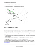
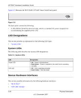
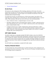
GS700AT Hardware Installation Guide Figure 3-2 illustrates the NETGEAR GS724AT Smart Switch back panel: Figure 3-2 The back panel contains the following: • A 100-240VAC/50-60 Hz universal input, which is a standard AC power receptacle for accommodating the supplied power cord. LED Designations This section provides an explanation for the following LED types: • "System LEDs" System LEDs The following table describes the System LED designations. Table 3-1. System LEDs LED Power LED FAN LED Designation • Off - Power is disconnected. • Solid Green - Power is supplied to the switch and is operating normally. • Off - FAN is operating normally. • Solid Yellow - FAN has failed. Device Hardware Interfaces This section provides information for the following hardware interfaces: • "RJ-45 Ports" • "SFP GBIC Module" 3-20 v1.0, December 2007 Physical Description
-
 1
1 -
2
-
3
-
4
-
5
-
6
-
7
-
8
-
9
-
10
-
11
-
12
-
13
-
14
-
15
-
16
-
17
-
18
-
 19
19 -
 20
20 -
 21
21 -
 22
22 -
 23
23 -
 24
24 -
 25
25 -
 26
26 -
 27
27 -
 28
28 -
 29
29 -
30
-
31
-
32
-
33
-
34
-
35
-
36
-
37
-
38
 |
 |