Netgear GS724AT GS724AT Hardware manual - Page 17
Installation, Step 1: Preparing the Site - configuration
 |
UPC - 606449056907
View all Netgear GS724AT manuals
Add to My Manuals
Save this manual to your list of manuals |
Page 17 highlights
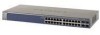
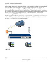
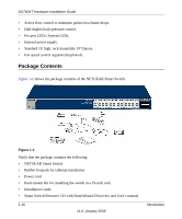
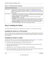
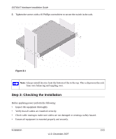
Chapter 2 Installation This chapter describes the installation procedures for your NETGEAR Smart Switch. Switch installation involves the following steps: "Step 1: Preparing the Site" "Step 2: Installing the Switch" "Step 3: Checking the Installation" "Step 4: Connecting Devices to the Switch" "Step 5: Installing an SFP GBIC Module" "Step 6: Applying AC Power" "Step 7: Managing the Switch through a Web Browser or the PC Utility for Initial Configuration" Step 1: Preparing the Site Before installing the switch, ensure the operating environment meets the requirements in the following table. Table 2-1. Site Requirements Characteristics Requirements Mounting Access • Desktop installations - Provide a flat table or shelf surface. • Rack-mount installations - Use a 19-inch (48.3-centimeter) EIA standard equipment rack that is grounded and physically secure. The rack-mount kit supplied with the switch is also required. Locate the switch in a position that allows access to the front panel RJ-45 ports, the ability to view the front panel LEDs, and easy safe access access to the power connector. v1.0, December 2007 2-29
-
 1
1 -
2
-
3
-
4
-
5
-
6
-
7
-
8
-
9
-
10
-
11
-
 12
12 -
 13
13 -
 14
14 -
 15
15 -
 16
16 -
 17
17 -
 18
18 -
 19
19 -
 20
20 -
 21
21 -
 22
22 -
23
-
24
-
25
-
26
-
27
-
28
-
29
-
30
-
31
-
32
-
33
-
34
-
35
-
36
-
37
-
38
 |
 |