Netgear GS728TPP GS728TP/GS728TPP/GS752TP Hardware Installation Guide - Page 13
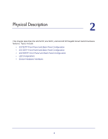
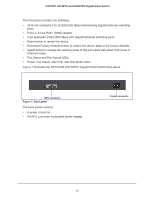
illustrates the NETGEAR GS728TPP Gigabit Smart Switch back panel.
 |
View all Netgear GS728TPP manuals
Add to My Manuals
Save this manual to your list of manuals |
Page 13 highlights
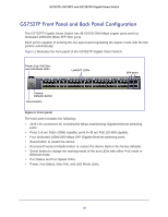
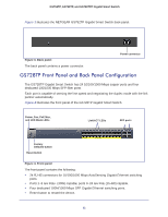
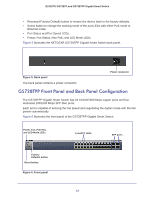
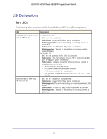
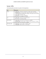
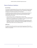
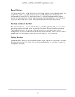
GS752TP, GS728TP, and GS728TPP Gigabit Smart Switch The front panel contains the following: • 24 RJ-45 connectors for 10/100/1000 Mbps AutoSensing Gigabit Ethernet switching ports. • Ports 1-24 are PoE+ (30W) capable. • Four dedicated 100M/1000 Mbps SFP Gigabit Ethernet switching ports. • Reset button to restart the device. • Recessed Factory Defaults button to restore the device back to the factory defaults. • Select button to change the working mode of the port LEDs with either PoE mode or Ethernet mode. • Port Status and Port Speed LEDs. • Power, Fan Status, Max PoE, and LED Mode LEDs. Figure 7 illustrates the NETGEAR GS728TPP Gigabit Smart Switch back panel. RPS connector Figure 7. Back panel The back panel contains: • A power connector • An RPS connector (redundant power supply) Power connector 13
-
 1
1 -
2
-
3
-
4
-
5
-
6
-
7
-
 8
8 -
 9
9 -
 10
10 -
 11
11 -
 12
12 -
 13
13 -
 14
14 -
 15
15 -
 16
16 -
 17
17 -
 18
18 -
19
-
20
-
21
-
22
-
23
-
24
-
25
-
26
-
27
-
28
-
29
-
30
-
31
-
32
-
33
-
34
-
35
-
36
 |
 |