Netgear GS752TP GS728TP/GS728TPP/GS752TP Hardware Installation Guide - Page 24
Step 6: Apply AC Power, The GS752TP, GS728TP
 |
View all Netgear GS752TP manuals
Add to My Manuals
Save this manual to your list of manuals |
Page 24 highlights
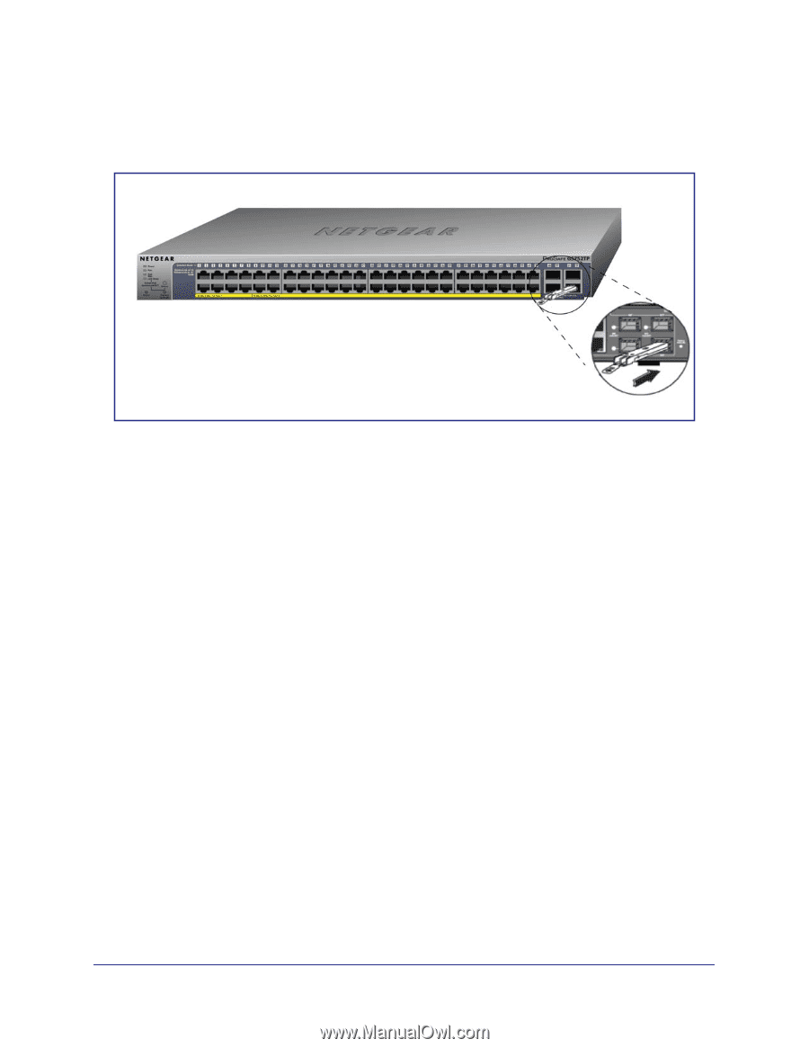
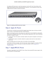
GS752TP, GS728TP, and GS728TPP Gigabit Smart Switch To install an SFP transceiver, insert the transceiver into the SFP port. Press firmly on the flange of the module to seat it securely into the connector. You can install up to three more Gigabit Ethernet modules using this procedure. Figure 12. Installing and SFP transceiver module Step 6: Apply AC Power The GS752TP, GS728TP, and GS728TPP Gigabit Smart Switch does not have an On/Off switch. Power is controlled by the power cord connection. Before connecting the power cord, select an AC outlet that is not controlled by a wall switch, which can turn off power to the switch. After selecting an appropriate outlet, use the following procedure to apply AC power: 1. Connect the end of the power connection cable to the power receptacle on the back of the switch. 2. Connect the AC power connection cable into a power source such as a wall socket or power strip. When you apply power, the Power LED on the switch's front panel lights. If the Power LED does not light, check that the power cable is plugged in correctly and that the power source is good. If this does not resolve the problem, refer to Appendix A, Troubleshooting. Step 7: Apply RPS DC Power This step is applicable to the GS728TPP only. Plug in the external RPS power supply to the RPS connector on the back panel. 25
-
 1
1 -
2
-
3
-
4
-
5
-
6
-
7
-
8
-
9
-
10
-
11
-
12
-
13
-
14
-
15
-
16
-
17
-
18
-
 19
19 -
 20
20 -
 21
21 -
 22
22 -
 23
23 -
 24
24 -
 25
25 -
 26
26 -
 27
27 -
 28
28 -
 29
29 -
30
-
31
-
32
-
33
-
34
-
35
-
36
 |
 |