Netgear GSM7224P GSM5212P/GSM7212P/GSM7212F/GSM7224P User Manual - Page 312
Click, to refresh the data on the screen and display the most current statistics., Designated Port
 |
View all Netgear GSM7224P manuals
Add to My Manuals
Save this manual to your list of manuals |
Page 312 highlights
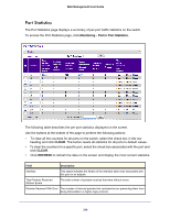
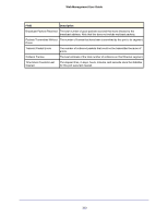
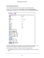
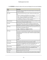
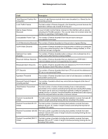
Web Management User Guide • Click REFRESH to refresh the data on the screen and display the most current statistics. Field ifIndex Port Type Port Channel ID Port Role STP Mode STP State Admin Mode LACP Mode Physical Mode Physical Status Link Status Link Trap Description This object indicates the ifIndex of the interface table entry associated with this port on an adapter. For normal ports this field will be 'normal.' Otherwise the possible values are: • Mirrored - This port is a participating in port mirroring as a mirrored port. Look at the Port Mirroring screens for more information. • Probe - This port is a participating in port mirroring as the probe port. Look at the Port Mirroring screens for more information. • Trunk Member - The port is a member of a Link Aggregation trunk. Look at the Port Channel screens for more information. If the port is a member of a port channel, the port channel's interface ID and name are shown. Otherwise "Disable" is shown. Each MST Bridge Port that is enabled is assigned a Port Role for each spanning tree. The port role will be one of the following values: Root Port, Designated Port, Alternate Port, Backup Port, Master Port or Disabled Port. The Spanning Tree Protocol Administrative Mode associated with the port or Port Channel. The possible values are: • Enable - Spanning tree is enabled for this port. • Disable - Spanning tree is disabled for this port. The port's current state Spanning Tree state. This state controls what action a port takes on receipt of a frame. If the bridge detects a malfunctioning port it will place that port into the broken state. The other five states are defined in IEEE 802.1D: • Disabled • Blocking • Listening • Learning • Forwarding • Broken The Port control administration state. The port must be enabled in order for it to be allowed into the network. The factory default is enabled. Indicates the Link Aggregation Control Protocol administration state. The mode must be enabled in order for the port to participate in Link Aggregation. Indicates The port speed and duplex mode. In auto-negotiation mode the duplex mode and speed are set from the auto-negotiation process. Indicates the port speed and duplex mode. Indicates whether the Link is up or down. Indicates whether or not the port will send a trap when link status changes. 312
-
 1
1 -
2
-
3
-
4
-
5
-
6
-
7
-
8
-
9
-
10
-
11
-
12
-
13
-
14
-
15
-
16
-
17
-
18
-
19
-
20
-
21
-
22
-
23
-
24
-
25
-
26
-
27
-
28
-
29
-
30
-
31
-
32
-
33
-
34
-
35
-
36
-
37
-
38
-
39
-
40
-
41
-
42
-
43
-
44
-
45
-
46
-
47
-
48
-
49
-
50
-
51
-
52
-
53
-
54
-
55
-
56
-
57
-
58
-
59
-
60
-
61
-
62
-
63
-
64
-
65
-
66
-
67
-
68
-
69
-
70
-
71
-
72
-
73
-
74
-
75
-
76
-
77
-
78
-
79
-
80
-
81
-
82
-
83
-
84
-
85
-
86
-
87
-
88
-
89
-
90
-
91
-
92
-
93
-
94
-
95
-
96
-
97
-
98
-
99
-
100
-
101
-
102
-
103
-
104
-
105
-
106
-
107
-
108
-
109
-
110
-
111
-
112
-
113
-
114
-
115
-
116
-
117
-
118
-
119
-
120
-
121
-
122
-
123
-
124
-
125
-
126
-
127
-
128
-
129
-
130
-
131
-
132
-
133
-
134
-
135
-
136
-
137
-
138
-
139
-
140
-
141
-
142
-
143
-
144
-
145
-
146
-
147
-
148
-
149
-
150
-
151
-
152
-
153
-
154
-
155
-
156
-
157
-
158
-
159
-
160
-
161
-
162
-
163
-
164
-
165
-
166
-
167
-
168
-
169
-
170
-
171
-
172
-
173
-
174
-
175
-
176
-
177
-
178
-
179
-
180
-
181
-
182
-
183
-
184
-
185
-
186
-
187
-
188
-
189
-
190
-
191
-
192
-
193
-
194
-
195
-
196
-
197
-
198
-
199
-
200
-
201
-
202
-
203
-
204
-
205
-
206
-
207
-
208
-
209
-
210
-
211
-
212
-
213
-
214
-
215
-
216
-
217
-
218
-
219
-
220
-
221
-
222
-
223
-
224
-
225
-
226
-
227
-
228
-
229
-
230
-
231
-
232
-
233
-
234
-
235
-
236
-
237
-
238
-
239
-
240
-
241
-
242
-
243
-
244
-
245
-
246
-
247
-
248
-
249
-
250
-
251
-
252
-
253
-
254
-
255
-
256
-
257
-
258
-
259
-
260
-
261
-
262
-
263
-
264
-
265
-
266
-
267
-
268
-
269
-
270
-
271
-
272
-
273
-
274
-
275
-
276
-
277
-
278
-
279
-
280
-
281
-
282
-
283
-
284
-
285
-
286
-
287
-
288
-
289
-
290
-
291
-
292
-
293
-
294
-
295
-
296
-
297
-
298
-
299
-
300
-
301
-
302
-
303
-
304
-
305
-
306
-
 307
307 -
 308
308 -
 309
309 -
 310
310 -
 311
311 -
 312
312 -
 313
313 -
 314
314 -
 315
315 -
 316
316 -
 317
317 -
318
-
319
-
320
-
321
-
322
-
323
-
324
-
325
-
326
-
327
-
328
-
329
-
330
-
331
-
332
-
333
-
334
-
335
-
336
-
337
-
338
-
339
-
340
-
341
-
342
-
343
-
344
-
345
-
346
-
347
-
348
-
349
-
350
-
351
-
352
-
353
-
354
-
355
-
356
-
357
-
358
-
359
-
360
-
361
-
362
-
363
-
364
-
365
-
366
-
367
-
368
-
369
-
370
-
371
-
372
-
373
-
374
-
375
-
376
-
377
-
378
-
379
-
380
-
381
-
382
-
383
-
384
-
385
 |
 |