Netgear GSM7224P GSM5212P/GSM7212P/GSM7212F/GSM7224P User Manual - Page 364
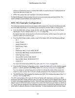
MAC ACL Example Configuration
 |
View all Netgear GSM7224P manuals
Add to My Manuals
Save this manual to your list of manuals |
Page 364 highlights
Web Management User Guide criteria to a particular queue or redirect the traffic to a particular port. A default deny all rule is the last rule of every list. 2. APPLY the access list to an interface in the inbound direction. ProSafe® Managed Switches allow ACLs to be bound to physical ports and LAGs. The switch software supports MAC ACLs and IP ACLs. MAC ACL Example Configuration The following example shows how to create a MAC-based ACL that permits Ethernet traffic from the Sales department on specified ports and denies all other traffic on those ports. 1. From the MAC ACL screen, create an ACL with the name Sales_ACL for the Sales department of your network (See MAC ACL on page 534). By default, this ACL will be bound on the inbound direction, which means the switch will examine traffic as it enters the port. 2. From the MAC Rules screen, create a rule for the Sales_ACL with the following settings: • ID: 1 • Action: Permit • Assign Queue ID: 0 • Match Every: False • CoS: 0 • Destination MAC: 01:02:1A:BC:DE:EF • Destination MAC Mask: 00:00:00:00:FF:FF • EtherType User Value: • Source MAC: 02:02:1A:BC:DE:EF • Source MAC Mask: 00:00:00:00:FF:FF • VLAN ID: 2 For more information about MAC ACL rules, see MAC Rules on page 536. 3. From the MAC Binding Configuration screen, assign the Sales_ACL to the interface gigabit ports 6, 7, and 8, and then click APPLY (See MAC Binding Configuration on page 538). You can assign an optional sequence number to indicate the order of this access list relative to other access lists if any are already assigned to this interface and direction. 4. The MAC Binding Table displays the interface and MAC ACL binding information (See MAC Binding Table on page 540). The ACL named Sales_ACL looks for Ethernet frames with destination and source MAC addresses and MAC masks defined in the rule. Also, the frame must be tagged with VLAN ID 2, which is the Sales department VLAN. The CoS value of the frame must be 0, which is the default value for Ethernet frames. Frames that match this criteria are permitted on interfaces 6, 7, and 8 and are assigned to the hardware egress queue 0, which is the default queue. All other traffic is explicitly denied on these interfaces. To allow additional traffic to enter these 364
-
 1
1 -
2
-
3
-
4
-
5
-
6
-
7
-
8
-
9
-
10
-
11
-
12
-
13
-
14
-
15
-
16
-
17
-
18
-
19
-
20
-
21
-
22
-
23
-
24
-
25
-
26
-
27
-
28
-
29
-
30
-
31
-
32
-
33
-
34
-
35
-
36
-
37
-
38
-
39
-
40
-
41
-
42
-
43
-
44
-
45
-
46
-
47
-
48
-
49
-
50
-
51
-
52
-
53
-
54
-
55
-
56
-
57
-
58
-
59
-
60
-
61
-
62
-
63
-
64
-
65
-
66
-
67
-
68
-
69
-
70
-
71
-
72
-
73
-
74
-
75
-
76
-
77
-
78
-
79
-
80
-
81
-
82
-
83
-
84
-
85
-
86
-
87
-
88
-
89
-
90
-
91
-
92
-
93
-
94
-
95
-
96
-
97
-
98
-
99
-
100
-
101
-
102
-
103
-
104
-
105
-
106
-
107
-
108
-
109
-
110
-
111
-
112
-
113
-
114
-
115
-
116
-
117
-
118
-
119
-
120
-
121
-
122
-
123
-
124
-
125
-
126
-
127
-
128
-
129
-
130
-
131
-
132
-
133
-
134
-
135
-
136
-
137
-
138
-
139
-
140
-
141
-
142
-
143
-
144
-
145
-
146
-
147
-
148
-
149
-
150
-
151
-
152
-
153
-
154
-
155
-
156
-
157
-
158
-
159
-
160
-
161
-
162
-
163
-
164
-
165
-
166
-
167
-
168
-
169
-
170
-
171
-
172
-
173
-
174
-
175
-
176
-
177
-
178
-
179
-
180
-
181
-
182
-
183
-
184
-
185
-
186
-
187
-
188
-
189
-
190
-
191
-
192
-
193
-
194
-
195
-
196
-
197
-
198
-
199
-
200
-
201
-
202
-
203
-
204
-
205
-
206
-
207
-
208
-
209
-
210
-
211
-
212
-
213
-
214
-
215
-
216
-
217
-
218
-
219
-
220
-
221
-
222
-
223
-
224
-
225
-
226
-
227
-
228
-
229
-
230
-
231
-
232
-
233
-
234
-
235
-
236
-
237
-
238
-
239
-
240
-
241
-
242
-
243
-
244
-
245
-
246
-
247
-
248
-
249
-
250
-
251
-
252
-
253
-
254
-
255
-
256
-
257
-
258
-
259
-
260
-
261
-
262
-
263
-
264
-
265
-
266
-
267
-
268
-
269
-
270
-
271
-
272
-
273
-
274
-
275
-
276
-
277
-
278
-
279
-
280
-
281
-
282
-
283
-
284
-
285
-
286
-
287
-
288
-
289
-
290
-
291
-
292
-
293
-
294
-
295
-
296
-
297
-
298
-
299
-
300
-
301
-
302
-
303
-
304
-
305
-
306
-
307
-
308
-
309
-
310
-
311
-
312
-
313
-
314
-
315
-
316
-
317
-
318
-
319
-
320
-
321
-
322
-
323
-
324
-
325
-
326
-
327
-
328
-
329
-
330
-
331
-
332
-
333
-
334
-
335
-
336
-
337
-
338
-
339
-
340
-
341
-
342
-
343
-
344
-
345
-
346
-
347
-
348
-
349
-
350
-
351
-
352
-
353
-
354
-
355
-
356
-
357
-
358
-
 359
359 -
 360
360 -
 361
361 -
 362
362 -
 363
363 -
 364
364 -
 365
365 -
 366
366 -
 367
367 -
 368
368 -
 369
369 -
370
-
371
-
372
-
373
-
374
-
375
-
376
-
377
-
378
-
379
-
380
-
381
-
382
-
383
-
384
-
385
 |
 |